A1000, 5 installation procedure – Yaskawa SI-EP3 PROFINET Technical Manual User Manual
Page 17
5 Installation Procedure
YASKAWA ELECTRIC
SIEP C730600 69A 1000-Series Option SI-EP3 Technical Manual
17
7.
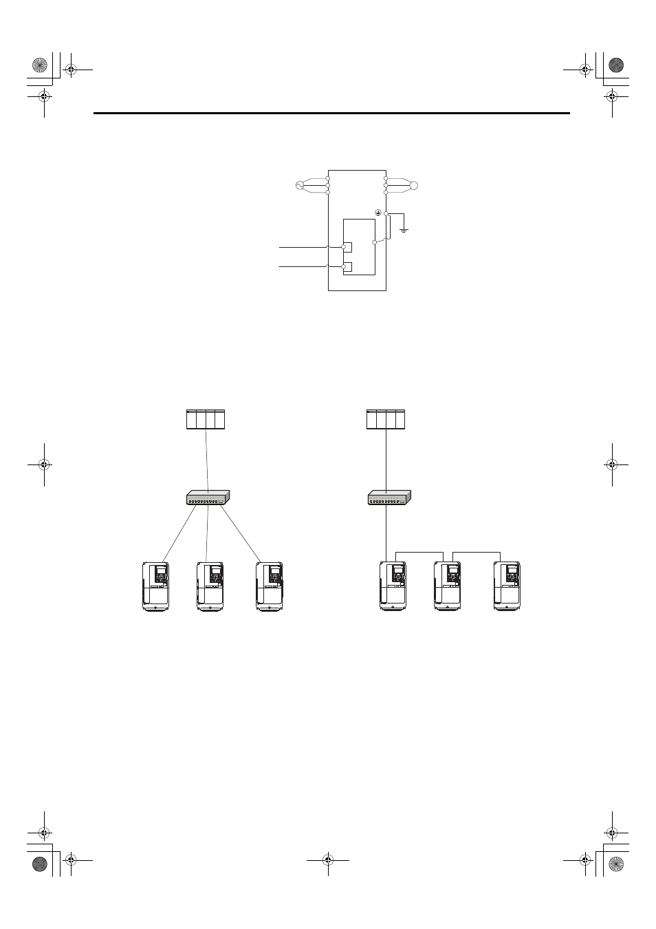
Use the second option modular connector CN1 port to daisy chain a series of drives where applicable.
Connection Diagram
Figure 8 Option Connection Diagram
Communication Cable Wiring
The option modular connector CN1 port 1 and port 2 act as a switch to allow for flexibility in cabling topology. For
example, a traditional star network topology may be employed by using a single port on the option. Alternatively,
a daisy-chained approach may be employed by using both option modular connector ports. This second
approach reduces the requirements of PROFINET switch ports.
Figure 8
Figure 9 Topology Options
<1> The ground wire provided in the option shipping package must be connected during
installation.
A1000
M
U/T1
V/T2
W/T3
R/L1
S/L2
T/L3
SI-EP3
PROFINET
Option
FE
PROFINET Master
PROFINET Cable
Motor
Power
PROFINET Cable
<1>
A1000
PLC
SWITCH
Yaskawa Drive
Yaskawa Drive
Yaskawa Drive
Yaskawa Drive
Yaskawa Drive
Yaskawa Drive
PLC
SWITCH
A1000
PROFINET_E_conditional.book 17 ページ 2015年2月25日 水曜日 午後5時17分