Yaskawa SI-EP3 PROFINET Technical Manual User Manual
Page 21
6 Related Drive Parameters
YASKAWA ELECTRIC
SIEP C730600 69A 1000-Series Option SI-EP3 Technical Manual
21
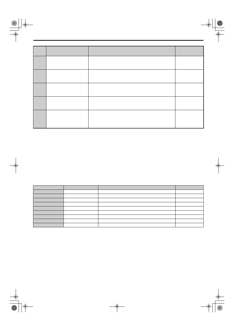
Table 7 Option Monitors
F7-34
(406)
Dynamic Input Assembly
Parameter 2
Sets configurable input 2.
Default: 0H
Min.: 0H
Max.: FFFFH
F7-35
(407)
Dynamic Input Assembly
Parameter 3
Sets configurable input 3.
Default: 0H
Min.: 0H
Max.: FFFFH
F7-36
(408)
Dynamic Input Assembly
Parameter 4
Sets configurable input 4.
Default: 0H
Min.: 0H
Max.: FFFFH
F7-37
(409)
Dynamic Input Assembly
Parameter 5
Sets configurable input 5.
Default: 0H
Min.: 0H
Max.: FFFFH
H5-11
(43C)
Communications ENTER Function
Selection
Select the function for the ENTER command that saves parameter data to
the drive.
0: Parameter changes are activated when ENTER command is written
1: Parameter changes are activated immediately without use of ENTER
command
Default: 1
Range: 0, 1
<1> To start and stop the drive with the option master device using serial communications, set b1-02 to 3. To control the drive frequency reference
via the master device, set b1-01 to 3.
<2> If F6-01 is set to 3 or 4, the drive will continue to operate when a fault is detected. Take safety measures, such as installing an emergency stop
switch.
<3> Available for software versions PRG: 1021 and later when using A1000. Refer to the instruction manual of a specific drive to determine if
settings 4 and 5 are available in the drive.
<4> Enabled in CLV, AOLV/PM, and CLV/PM control modes (A1-02 = 3, 6, or 7). When enabled, d5-01 determines whether the value is read as the
Torque Limit value (d5-01 = 0) or read as the Torque Reference value (d5-01 = 1). In CLV/PM, this value is read as the Torque Limit.
<5> The setting specifies that the Torque Reference or Torque Limit is to be provided via network communications (F6-06 = 1). The motor may
rotate if no torque reference or Torque Limit is supplied from the PLC.
<6> Cycle power for setting changes to take effect.
<7> If F7-13 is set to 0, then all IP Addresses (F7-01 to F7-04) must be unique.
<8> Set F7-01 to F7-12 when F7-13 is set to 0.
<9> Set F7-15 when F7-14 is set to 0 or 2.
<10> If a value other than 0 is assigned to parameters F7-23 to F7-27 and F7-33 to F7-37 by the drive, that value will take precedent over a value set
by the configuration software. If the value in the drive is 0 (default), the value from the configuration software is used.
No.
Name
Description
Value Range
U6-80 to U6-83
Online IP Address
SI-EP3 IP Address, U6-80 is the most significant octet.
0 to 255
U6-84 to U6-87
Online Subnet
Subnet, U6-94 is the most significant octet.
0 to 255
U6-88 to U6-91
Online Gateway
Gateway, U6-88 is the most significant octet.
0 to 255
U6-92
Online Speed
CN1 Port 1 Link Speed
10, 100
U6-93
Online Duplex
CN1 Port 1 Duplex Setting
0: Half, 1: Full
U6-94
Online Speed
CN1 Port 2 Link Speed
10, 100
U6-95
Online Duplex
CN1 Port 2 Duplex Setting
0: Half, 1: Full
U6-98
First Fault
First Option Board Fault
–
U6-99
Current Fault
Current Option Board Fault
–
No.
(Addr.
Hex)
Name
Description
Values
PROFINET_E_conditional.book 21 ページ 2015年2月25日 水曜日 午後5時17分