8 cc-link data table, Remote i/o, 8cc-link data table – Yaskawa 1000 Series Drive Option - CC-Link Installation User Manual
Page 24: Plc → drive
24
YASKAWA ELECTRIC TOBP C730600 44A YASKAWA AC Drive-Option Card CC-Link Installation Manual
8 CC-Link Data Table
8
CC-Link Data Table
◆
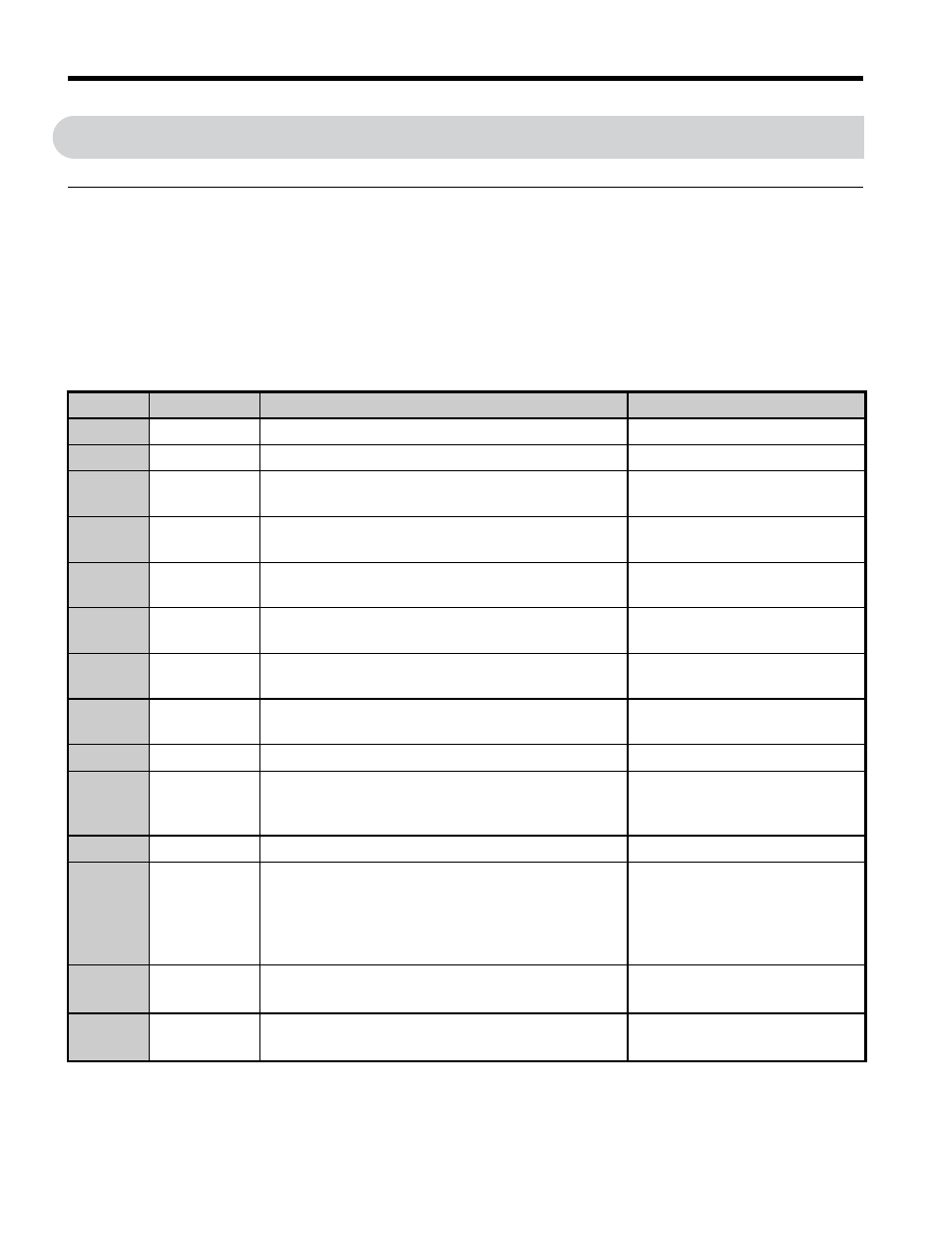
Remote I/O
The drive takes up a single station address in the buffer memory or the PLC. The table below
shows the drive I/O as seen from the PLC side.
Note: Refer to the PLC’s programming manual for information on the PLC’s buffer memory.
■
PLC
→ Drive
Table 6 Remote I/O Table (PLC
→ Drive)
Signal
Name
Description
Default
RY0
Forward Run
ON: Forward Run Command, OFF: Stop
–
RY1
Reverse Run
ON: Reverse Run Command, OFF: Stop
–
RY2
Terminal S3
Function
Multi-function input: H1-03
(H1-03 = 24: External Fault)
RY3
Terminal S4
Function
Multi-function input: H1-04
(H1-04 = 14: Fault Reset)
RY4
Terminal S5
Function
Multi-function input: H1-05
(H1-05 = 3: Multi-Step Speed 1)
RY5
Terminal S6
Function
Multi-function input: H1-06
(H1-06 = 4: Multi-Step Speed 2)
RY6
Terminal S7
Function
Multi-function input: H1-07
(H1-07 = 6: Jog Reference)
RY7
Terminal S8
Function
Multi-function input: H1-08
(H1-08=8, baseblock command)
RY8
Reserved
–
–
RY9
Drive Output
Interrupt
ON: Motor coasts to stop.
OFF: Drive will begin operating as soon as a Run
command is given.
–
RYA
External Fault ON: External Fault Input (EF0)
–
RYB
Motor
Revolutions /
Output
Frequency
Switch
Data contents for the remote register RW
R1
switches
between motor revolutions and output frequency.
Motor rotations are displayed
when not in V/f or OLV for PM.
RYC
Monitor
Reference
ON: Monitor data specified in the monitor code is set
to remote register RW
R0
.
–
RYD
Frequency
Reference 1
Frequency set to remote register RW
W1
becomes the
operating frequency for the drive.
–