SMA WB 5000 Installation User Manual
Page 48
Replacing the varistors
SMA
Technology AG
Page 48
WB50_60-11:SE4005
Installation Guide
4.
Using a continuity tester, check all the varistors to see if there is a conducting
connection between connectors 2 and 3. If not, then that varistor is not working.
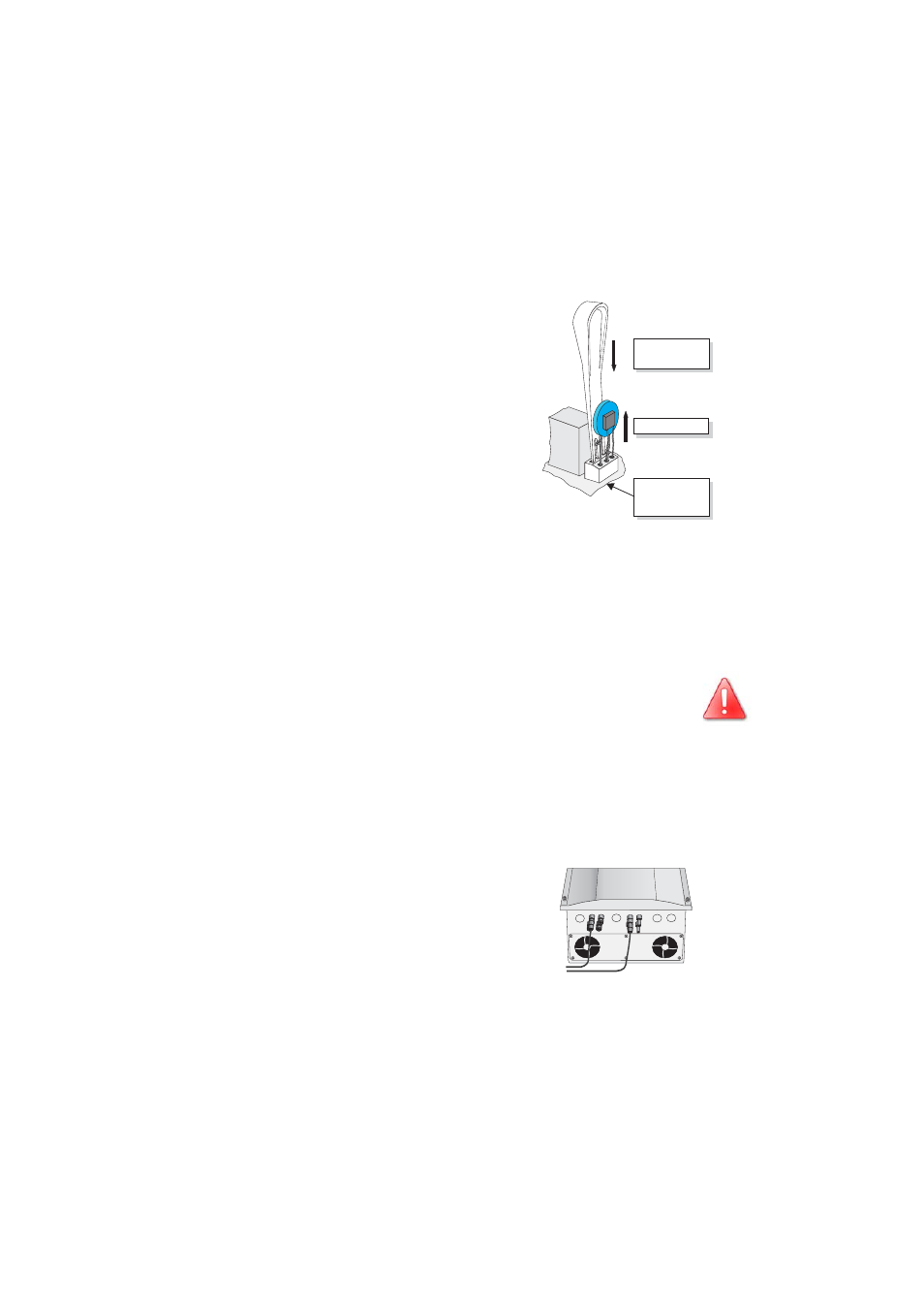
5.
Replace the varistor concerned with a new one
as shown in the drawing to the right. Ensure the
varistor is installed the right way round! If you
do not receive a special tool for operating the
terminal clamps with your replacement
varistors, please contact SMA. As an
alternative, the terminal contacts can be
operated using a suitable screwdriver. Since the
failure of one varistor is generally due to factors
that affect all varistors in a similar way
(temperature, age, inductive overvoltages), it is
highly recommended that you replace both
varistors, not just the one that is obviously
defective. The varistors are specially
manufactured for use in the Windy Boy 5000 /
6000 and are not commercially available. They
must be ordered directly from SMA
Technologie AG (SMA order code: "SB-TV4“).
In case there are no spare varistors available the Windy Boy 5000
/ 6000 still can feed electricity into the grid. The input is not protect-
ed against overvoltages in this case. Replacement varistors should
be obtained as soon as possible. In systems with a high risk of ov-
ervoltages, the Windy Boy 5000 / 6000 should not be operated
with defective varistors.
6.
Attach the cover to the enclosure of the Windy Boy 5000 / 6000 by tightening
the six screws. Don’t forget the lock washers. The notches of the lock washers
should face to the lid.
7.
Connect the DC plug connector.
8.
Close the unnecessary DC input sockets with the
caps included in the delivery.
Insert the special tool to
open the terminal.
The pole with the small loop
(crimp) must be fitted to
terminal 1 when replacing
the varistor.
Remove the varistor.
1 2
3
+ +
- -