3 procedure for model 13/1, Procedure for model 13/1 – SMA SC 400HE Installation User Manual
Page 59
SMA Solar Technology AG
External Connections
Installation Guide
SCxxxHE-IEN104432
59
6. Mount the Plexiglas cover and front sliding plate, see 6.2.1 ”Mounting and Dismounting the
Plexiglas Cover and Sliding Plate” (page 55).
7. Connect the AC cable to the copper bars from the outside.
6.2.3 Procedure for Model 13/1
1. Remove the Plexiglas cover and front sliding plate, see 6.2.1 ”Mounting and Dismounting the
Plexiglas Cover and Sliding Plate” (page 55).
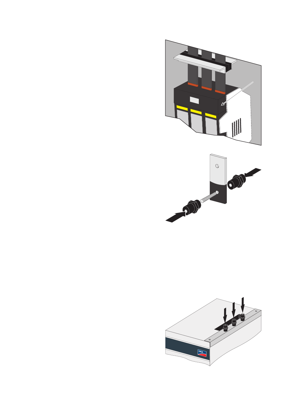
4. Connect the copper bars to the fuse load
disconnection unit (E) in the AC cabinet.
5. Mount the copper bars to the insulators. For this
purpose, screw the setscrews included in the delivery
into the still unused insulators and fasten them to the
other insulators through the copper bars. In this
manner, the two insulators function like locknuts.
2. Mount the three insulators next to the opening in the
roof of the switch cabinet for the copper bars.
E