3 handling the connection terminals, 4 sensors and digital outputs, Handling the connection terminals – SMA SC 100 Indoor Installation User Manual
Page 31: Sensors and digital outputs
SMA Solar Technology AG
Electrical Connection
Installation Guide
SC-100-IEN093231
31
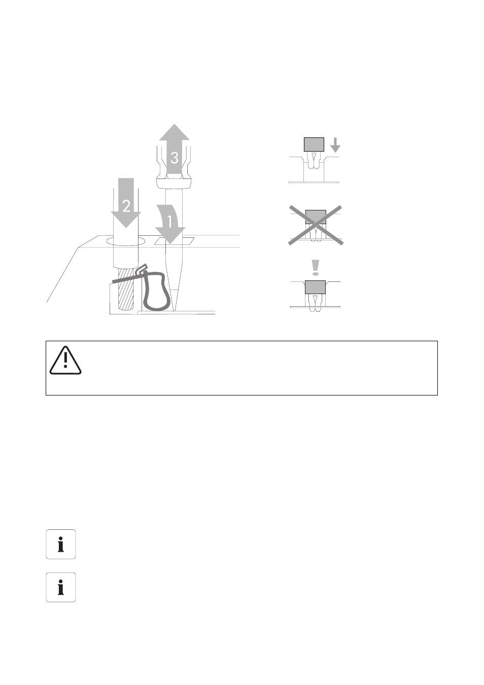
7.1.3 Handling the Connection Terminals
The following figure shows the correct method for handling the terminals used for connecting external
cables to the control terminal strip. The connection terminals are designed as maintenance-free spring-
loaded terminals that can be operated using a suitable screwdriver.
Figure 7.4: Handling the connection terminals (source: Wago)
7.1.4 Sensors and Digital Outputs
Two analog sensors and one PT100 temperature sensor can be connected to the Sunny Central. The
connection is made in the device's connection area. Please refer to the provided wiring diagram for
the signal assignment of the connection terminals.
Further information about the connection and parameterization of analog sensors is contained in the
Sunny Central user manual. We recommend equipping the first sensor inputs with an overvoltage
protector, available as an option. The sensors are connected directly to the overvoltage protector, see
figure 7.3.
WARNING!
The connections should only be made under voltage-free conditions!
Please note the connection possibility of the analog sensors in four-wire or two-wire system
and the required transducers, if necessary.
Please take note of the comprehensive description in the Sunny Central user manual
provided.