2 connecting the ethernet hardware – HEIDENHAIN SHB Data Interfaces for HEIDENHAIN User Manual
Page 65
7 – 66
HEIDENHAIN Service Manual for Data Interfaces
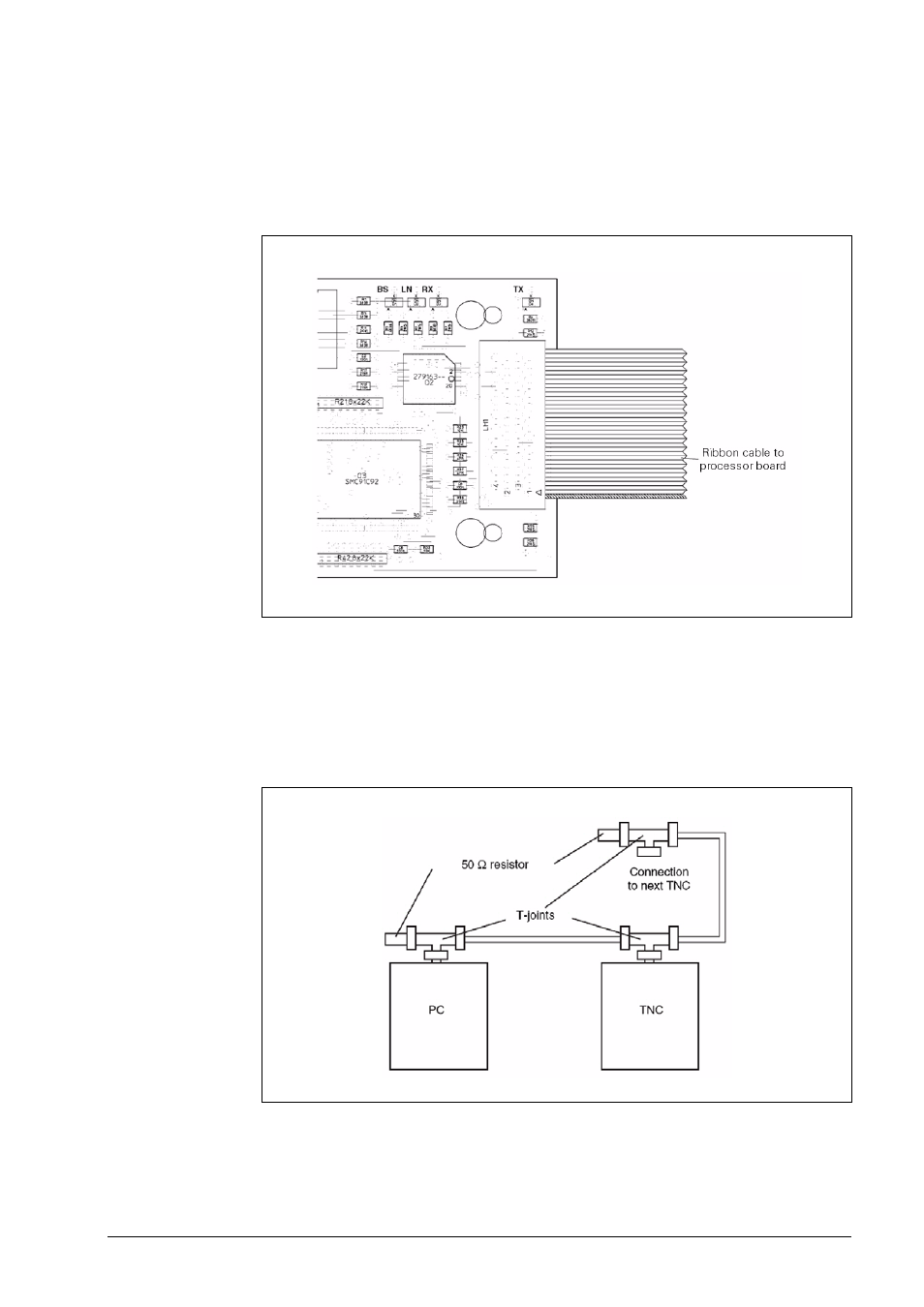
Function of the green LEDs on the ETHERNET board
BS (D1), Bus Select:
Access to the Ethernet controller by the CPU of the TNC
This LED must blink when the control is started!
LN (D2), Link:
Link signal received from server
RX (D3), Received:
Data are received
TX (D4), Transmitted:
Data are transmitted
7.2 Connecting the Ethernet Hardware
X26, 10Base2
The maximum cable length is 185 m.
If longer cables are required, an additional amplifier must be used.
The minimum distance between two T-connectors is 0.5 m.
The number of T-connectors must not exceed 30.
Cable ends not in use must be terminated by 50 ohms resistors.