9 showing the workpiece in the working space, Application – HEIDENHAIN iTNC 530 (606 42x-01) ISO programming User Manual
Page 556
556
MOD Functions
1
7.9 Sho
w
ing the W
o
rk
piece in the W
o
rk
ing Space
17.9
Showing the Workpiece in the
Working Space
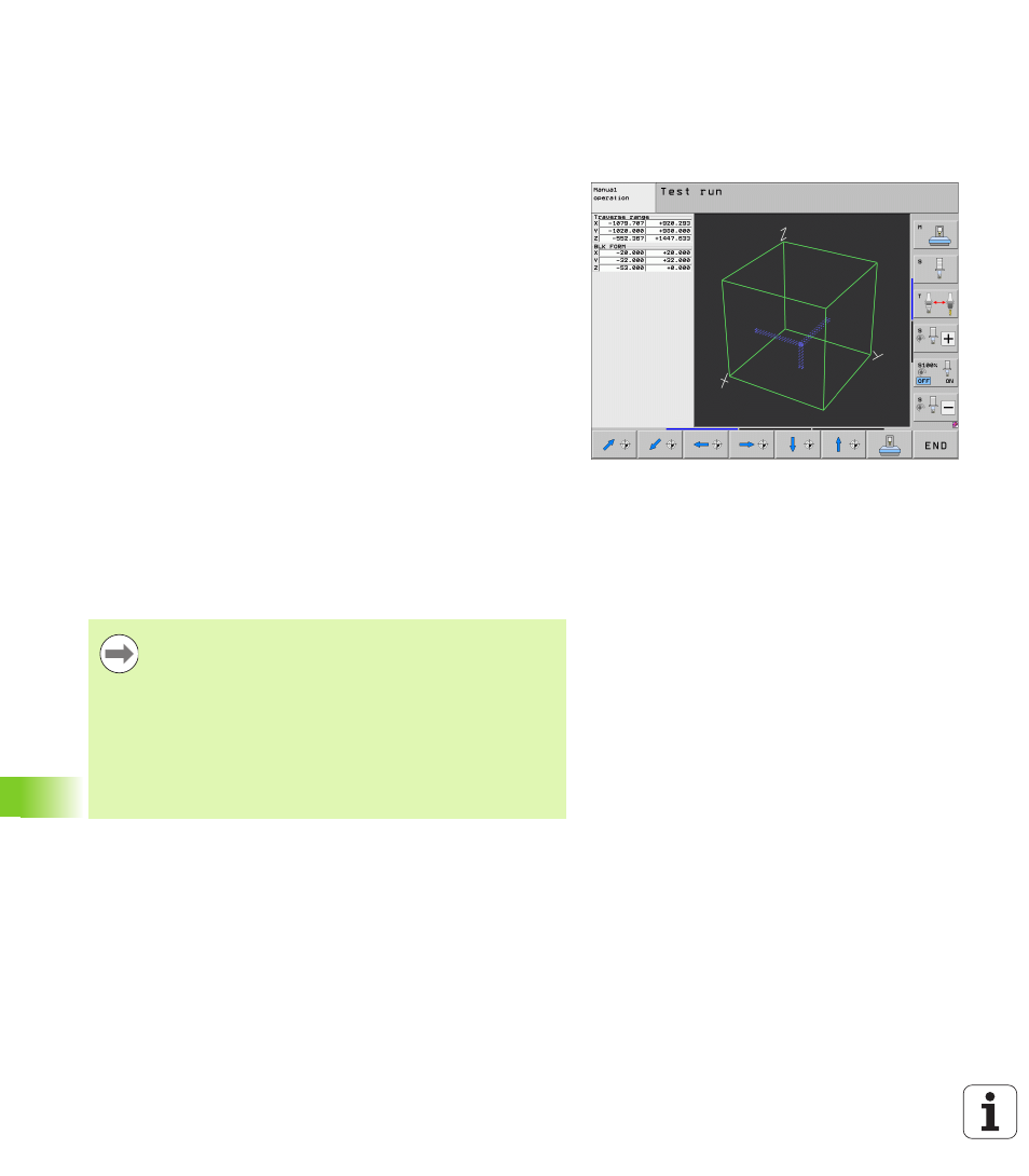
Application
This MOD function enables you to graphically check the position of the
workpiece blank in the machine’s working space and to activate work
space monitoring in the Test Run mode of operation.
The TNC displays a transparent cuboid for the working space. Its
dimensions are shown in the Traverse range table (default color is
green). The TNC takes the dimensions for the working space from the
machine parameters for the active traverse range. Since the traverse
range is defined in the reference system of the machine, the datum of
the cuboid is also the machine datum. You can see the position of the
machine datum in the cuboid by pressing the soft key M91 in the 2nd
soft-key row (default color is white).
Another transparent cuboid represents the workpiece blank. Its
dimensions are shown in the BLK FORM table (default color is blue). The
TNC takes the dimensions from the workpiece blank definition of the
selected program. The workpiece cuboid defines the coordinate
system for input. Its datum lies within the traverse-range cuboid. You
can view the position of the active datum within the traverse range by
pressing the “Show workpiece datum” soft key (2nd soft-key row).
For a test run it normally does not matter where the workpiece blank
is located within the working space. However, if you test programs
that contain movements with M91 or M92, you must graphically shift
the workpiece blank to prevent contour damage. Use the soft keys
shown in the following table.
If you want to perform a graphical collision test (software
option), you may need to graphically shift the reference
point in such a manner that no collision warnings are
generated.
Press the “Show the workpiece datum in the working
space” soft key to see the position of the workpiece blank
in the machine coordinate system. You must then place
your workpiece at these coordinates on the machine table
in order to ensure the same conditions during machining
as during the collision test.