3 fixture monitoring (software option), Fundamentals – HEIDENHAIN iTNC 530 (606 42x-01) ISO programming User Manual
Page 335
HEIDENHAIN iTNC 530
335
1
1
.3 Fixt
ur
e Monit
o
ri
ng (Sof
tw
ar
e Option)
11.3 Fixture Monitoring (Software
Option)
Fundamentals
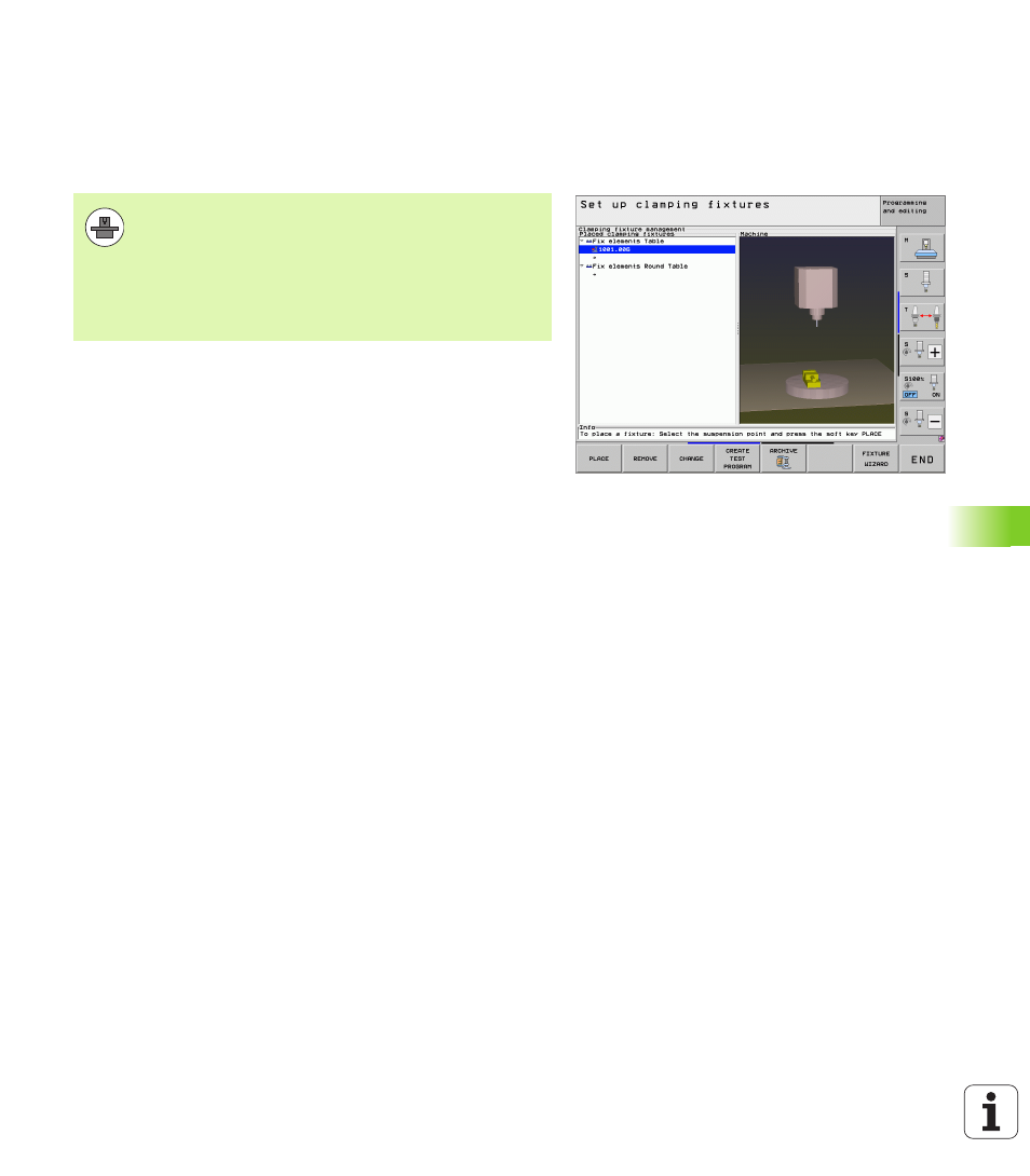
Using the fixture management in the Manual operating mode, you can
place simple fixtures in the working space of the machine in order to
implement collision monitoring between the tool and the fixture.
Several work steps are required to place fixtures
Model the fixture template
On its Web site, HEIDENHAIN provides fixture templates such as
vises or jaw chucks in a fixture template library (see “Fixture
templates” on page 336), that were created with the PC program
KinematicsDesign. The machine tool builder can model additional
fixture templates and provide you with them. The fixture templates
have the file name extension cft
Set the fixture parameter values: FixtureWizard
With the FixtureWizard you define the exact dimensions of the
fixture by entering parameters values in the fixture template. The
FixtureWizard is available as a component of the TNC fixture
management. It generates a placeable fixture with concrete
dimensions defined by you, (see “Setting parameter values for the
fixture: FixtureWizard” on page 336). Placable fixture templates
have the file name extension cfx
Place the fixture on the machine
In an interactive menu the TNC guides you through the actual
measurement process. The measurement process consists
essentially of the performance of various probing functions on the
fixture and entering variable sizes, for example the jaw gap of a vise
(see “Placing the fixture on the machine” on page 338)
Check the position of the measured fixture
After you have placed the fixture, you can have the TNC create a
measuring program as needed with which you can have the actual
position of the placed fixture compared with the nominal position. If
the deviations between the nominal and actual positions are too
large, the TNC issues an error message (see “Check the position of
the measured fixture” on page 340)
Your machine tool builder must define permissible
location points in the kinematic description before you can
use the fixture monitoring. The machine tool manual
provides further information.
Your machine has to feature a 3-D touch probe for
workpiece measurement. Otherwise you cannot locate
the fixture on the machine.