HEIDENHAIN iTNC 530 (606 42x-01) ISO programming User Manual
Page 404

404
Programming: Multiple Axis Machining
12.2 The PLANE F
unction: Tilting the W
o
rk
ing Plane (Sof
tw
ar
e Option 1)
Example for a machine with a rotary table C and a tilting table A.
Programmed function: PLANE SPATIAL SPA+0 SPB+45 SPC+0
Selecting the type of transformation (entry optional)
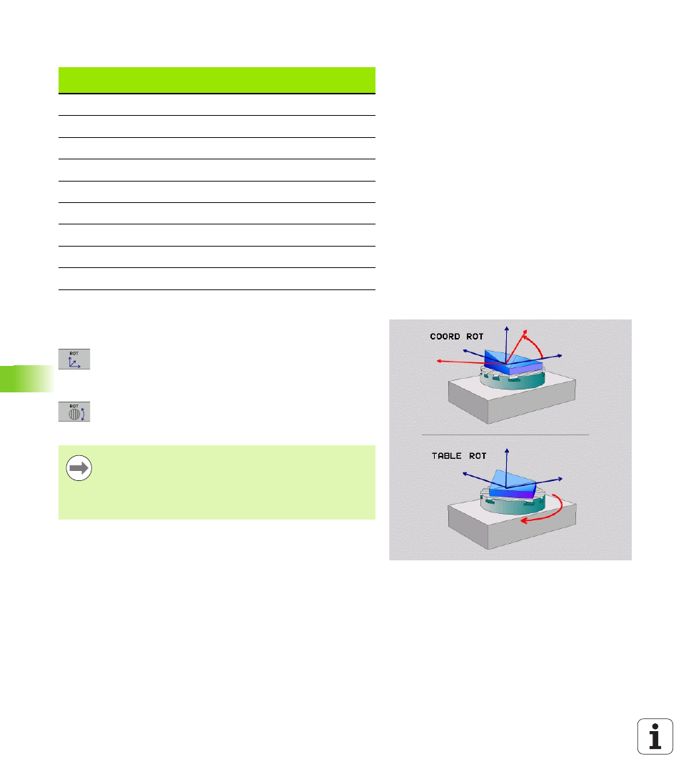
On machines with C-rotary tables, a function is available for specifying
the type of transformation:
U
COORD ROT
specifies that the PLANE function should
only rotate the coordinate system to the defined
tilting angle. The rotary table is not moved; the
compensation is purely mathematical.
U
TABLE ROT
specifies that the PLANE function should
position the rotary table to the defined tilting angle.
Compensation results from rotating the workpiece.
Limit switch
Starting
position
SEQ
Resulting axis
position
None
A+0, C+0
not prog.
A+45, C+90
None
A+0, C+0
+
A+45, C+90
None
A+0, C+0
–
A–45, C–90
None
A+0, C-105
not prog.
A–45, C–90
None
A+0, C-105
+
A+45, C+90
None
A+0, C-105
–
A–45, C–90
–90 < A < +10
A+0, C+0
not prog.
A–45, C–90
–90 < A < +10
A+0, C+0
+
Error message
None
A+0, C–135
+
A+45, C+90
When the PLANE AXIS function is used, COORD ROT and
TABLE ROT
are nonfunctional.
If you use the TABLE ROT function in conjunction with a
basic rotation and a tilting angle of 0, then the TNC tilts the
table to the angle defined in the basic rotation.
