01_nd1100_quickreference_en, Nd 1100 quadra-chek, Setup – HEIDENHAIN ND 1100 Quick Start User Manual
Page 3
1
ND 1100 QUADRA-CHEK
English
Setup
For detailed description, see www.heidenhain.de
Before Power up
Electrical connection
Line voltage:
100 V~ to 240 V~
(–15 % to +10 %)
Line frequency: 47 Hz to 63 Hz
Line fuse:
T1600 mA, 250 V
5 x 20 mm
Power connector wiring
L: Line voltage (brown)
N: Neutral (blue)
Earth ground (yellow/green)
Danger of electrical shock!
• Do not open the enclosure
• Never use 3-wire to 2-wire adapters
or allow the ground connection to
the ND 1100 to be interrupted or
disconnected.
Caution
Changes to the power cable may be
made only by an electrical technician.
Caution
Do not connect encoders or other
equipment to the ND 1100 when the
power is on.
Safety Considerations
General accepted safety precautions
must be followed when operating the
ND 1100. Failure to observe these
precautions could result in damage to
the equipment, or injury to personnel.
It is understood that safety rules within
individual companies vary. If a conflict
exists between the material contained
in this guide or the and the rules of a
company using this system, the more
stringent rules should take precedence.
Controls and Displays
A
LCD screen
B
Soft keys:
Change to support
functions
C
Axis keys:
Zero or preset datums
D
Command keys:
Control
measurement
E
Arrow cursor keys:
Menu
navigation
F
Fast track keys:
Programmable
for frequently used functions
G
Numeric keypad:
Enter numeric
data
H
Send key:
Transmit
measurement data to PC, USB
printer or USB drive
I
LCD on/off key:
Turn LCD on or
off, clear data, datums and skew
alignments
Connections rear side
1
Power switch
2
Power connection with fuse
3
Ground
(protective ground)
4
Encoder inputs,
X, Y, Z, Q axis
for linear and rotary encoders.
Interface specified at the time of
purchase.
5
RS-232-C interface
for PC
connection. RS-232 cable must
not include crossovers.
6
Touch probe connector
(optional)
7
Unused
Connections side view
8
Audio out,
for 3,5 mm
headphone /speaker jack,
monaural, 8 Ohm
9
USB type A interface
for printer
or data storage
10 Remote accessory interface
RJ-45 for optional foot switch or
keypad accessory. Two optional
remote accessories can be used
simultaneously using an RJ-45
splitter.
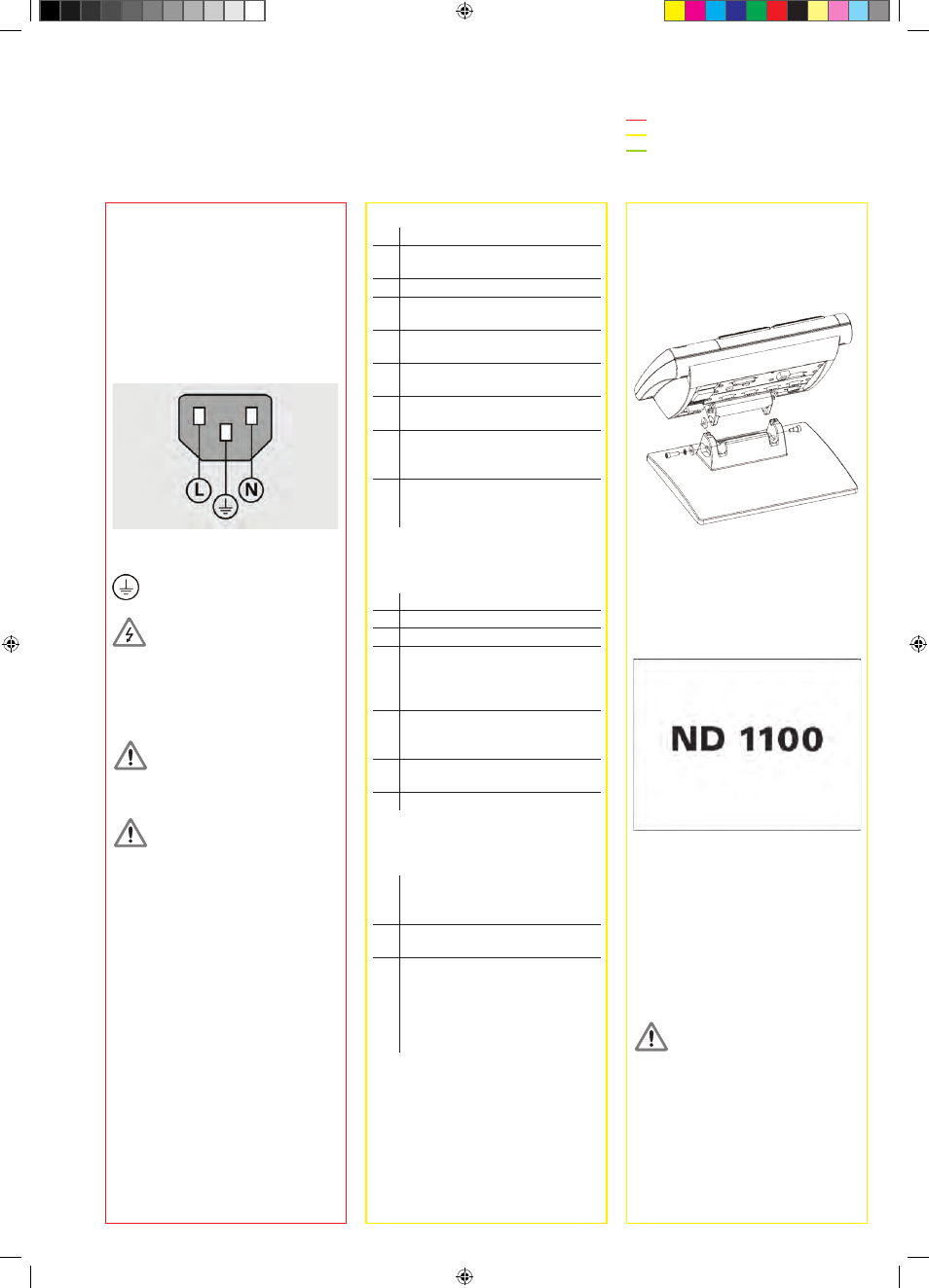
Mounting
The ND 1100 is secured to the swivel
slots of the mounting stand or arm
mount by a shoulder screw, a cap
screw mount is shown and associated
washers.
Initial power up
• Press the POwER SwITCH to power
the ND 1100. The startup screen is
displayed.
• Press the FINISH key to display the
current axis positions on the DRO
screen.
Software setup
The operating parameters of the
ND 1100 must be configured prior
to using it for the first time, and any
time measurement, reporting or
communication requirements change.
Settings will be retained until:
• The data-backup battery is changed
• The data and settings are cleared
• Software upgrades are performed
Caution
Setup parameters control the operation
of the ND 1100 and are password-
protected. Only qualified personnel
should be given password access to
setup screens.
1. Access setup menu
Press the MENU key and then press
the SETUP soft key. The setup menu is
displayed.
Very important
Please note
For your information