D-sub connection ext – HEIDENHAIN ND 261 v.2 User Manual
Page 5
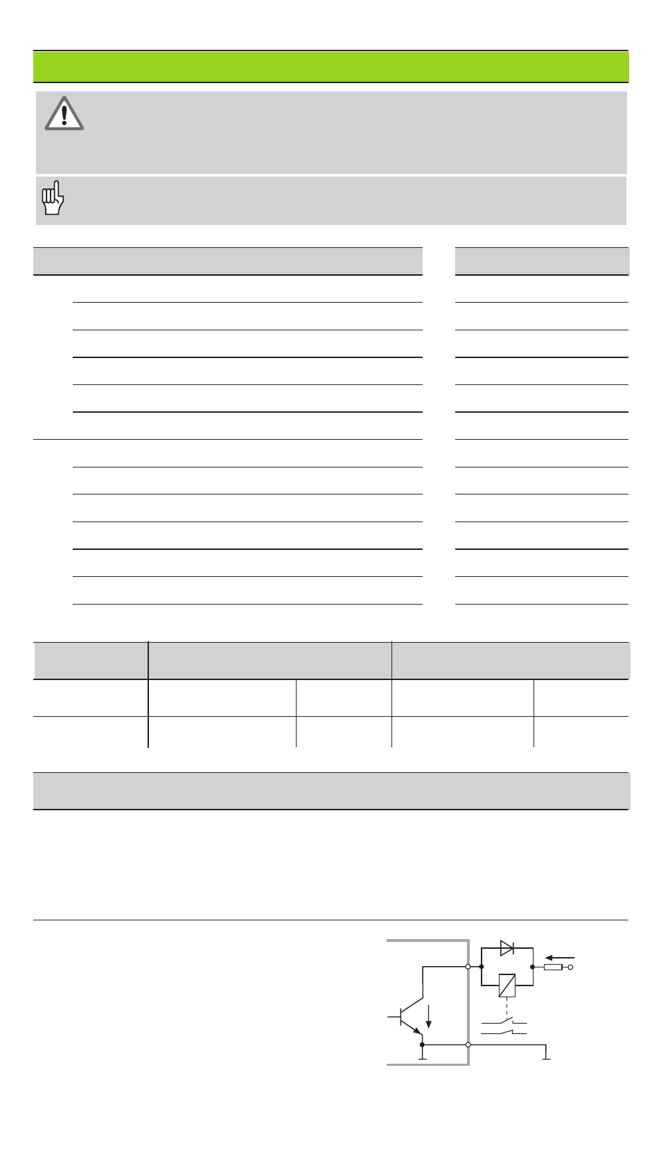
Outputs
Inputs
Use only shielded cable!
Connect the shield to the connector housing.
B
UCE
E
C
Pin 1.10
0 V
+ UB
≤
32 V
I
≤
100 mA
D-Sub Connection EXT
Pin
Function
Pin
Function
15
Meas. value
≥
trigger limit A1 (P62)
1
0 V
16
Meas. value
≥
trigger limit A2 (P63)
10
0 V
17
Meas. value < lower sorting limit (P18)
5
Do not use
18
Meas. value > upper sorting limit (P19)
6
Do not use
19
Error
(see “Error Messages” )
7
Do not use
14
Display value is zero
8
Do not use
2
Reset display to zero, clear error message
9
Do not use
3
Preset display to value from P79
12
Do not use
25
Cross over reference marks
13
Do not use
4
Ignore reference mark signal
24
Do not use
22
Pulse: output the measured value
11
Vacant
23
Contact: output the measured value
20
Vacant
21
Vacant
Signal levels
LOW
HIGH
Inputs
–0.5 V
≤
U
≤
0.9 V
I
≤
6 mA
3.9 V
≤
U
≤
15 V
Outputs
U
≤
0.4 V
I
≤
100 mA
U
≤
32 V
I
≤
10 µA
Description of input and output signals
Input signals
• Internal pull-up resistor 1 k
Ω
• Triggering by make contact against 0 V or
•
LOW level over TTL component
• Delay for Zero reset/Preset: t
d
≤
2 ms
• Minimum pulse duration for all signals: t
min
≥
42 ms
Output signals
• Open collector outputs,
•
active LOW
• Signal output delay:
•
t
d
≤
42 ms
• Zero crossover signal
minimum duration,
trigger outputs A1, A2:
t
0
≥
180 ms
Note that these times will increase if features are active (such as the sorting
mode) or if the measured values are being displayed in degrees/minutes/sec-
onds.
Danger to internal components!
Voltage sources from external circuitry must conform to the recommenda-
tions in EN 50178 for low-voltage electrical separation. Connect inductive
loads only with a quenching diode parallel to the inductance.