Data output – HEIDENHAIN ND 261 v.2 User Manual
Page 4
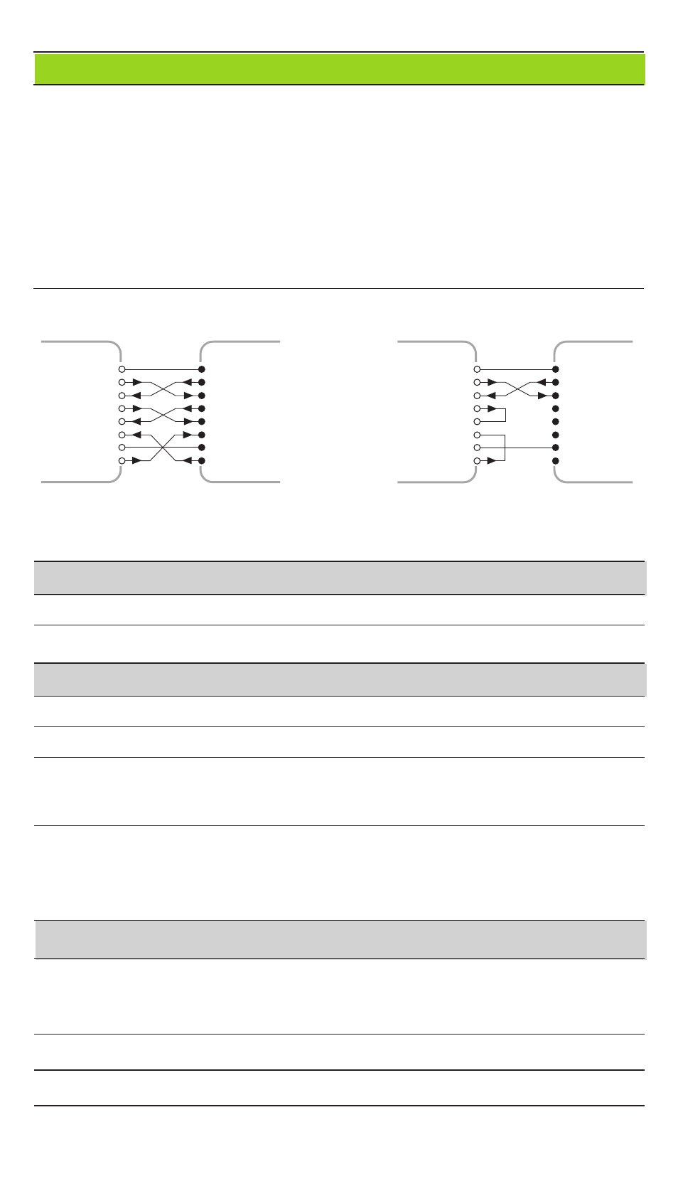
CHASSIS GND: Chassis Ground; TXD: Transmitted Data, RXD: Received Data,
RTS: Request To Send, CTS: Clear To Send; DSR: Data Set Ready; SIGNAL GND:
Signal Ground; DTR: Data Terminal Ready
Signals
Signal level "active"
Signal level "not active"
TXD, RXD
–3 V to –15 V
+3 V to +15 V
RTS, CTS, DSR, DTR
+3 V to +15 V
-3 V to -15 V
Data transfer format and control characters
Format
ASCII code
Data word
1 start bit, 7 data bits, parity bit (even parity), 2 stop bits
Control characters Call measured value: STX (CTRL B), interrupt DC3 (CTRL S),
resume DC1 (CTRL Q)
Enquire error message: ENQ (CTRL E)
Sequence
• Sign • Numerical value with up to 2 decimal points
• Blank space (or ? for error)
• Comparison result (<, >, =; ? if P18 > P19) or blank space
• 1 blank space • Carriage return • Line feed
Storage and transfer times
The duration of data transfer depends on the selected baud rate and the number of
additional line feeds. Display of degrees, minutes and seconds increases the storage
and transfer times.
Latch signal
STX (CTRL B) EXT (pulse)
EXT (contact) PRINT
Storage time
≤
1 ms
≤
1 µs
≤
5 ms
≤
42 ms
Transfer time
≤
44 ms
≤
44 ms
≤
48 ms
≤
85 ms
1
GND
2
3
4
5
6
20
7
TXD
RXD
RTS
CTS
DSR
GND
SIGNAL
DTR
CHASSIS
1
GND
2
3
4
5
6
20
7
TXD
RXD
RTS
CTS
DSR
GND
SIGNAL
DTR
CHASSIS
ND
1
1
GND
2
3
4
5
6
20
7
TXD
RXD
RTS
CTS
DSR
GND
SIGNAL
DTR
CHASSIS
2
3
4
5
6
20
7
ND
GND
TXD
RXD
RTS
CTS
DSR
GND
SIGNAL
DTR
CHASSIS
Data Output
There are three ways to output data:
➤ PRINT function: Press the MOD key (this method can be inhibited with
operating parameter P86); or
➤ Input the command STX (CTRL B) over the RXD input; or
➤ Input a latch command over the D-sub connection EXT.
A connecting cable (to a PC, for example) is available from HEIDENHAIN
(Id.-Nr. 274 545 ..); cable length up to 20 m (66 ft).
Operating parameters for data output: P50, P51
Wiring and pin layout
Connecting cable is either completely wired (left) or only partially wired (right).