D-sub connection ext (25-pin, male) – HEIDENHAIN ND 286 User Manual
Page 5
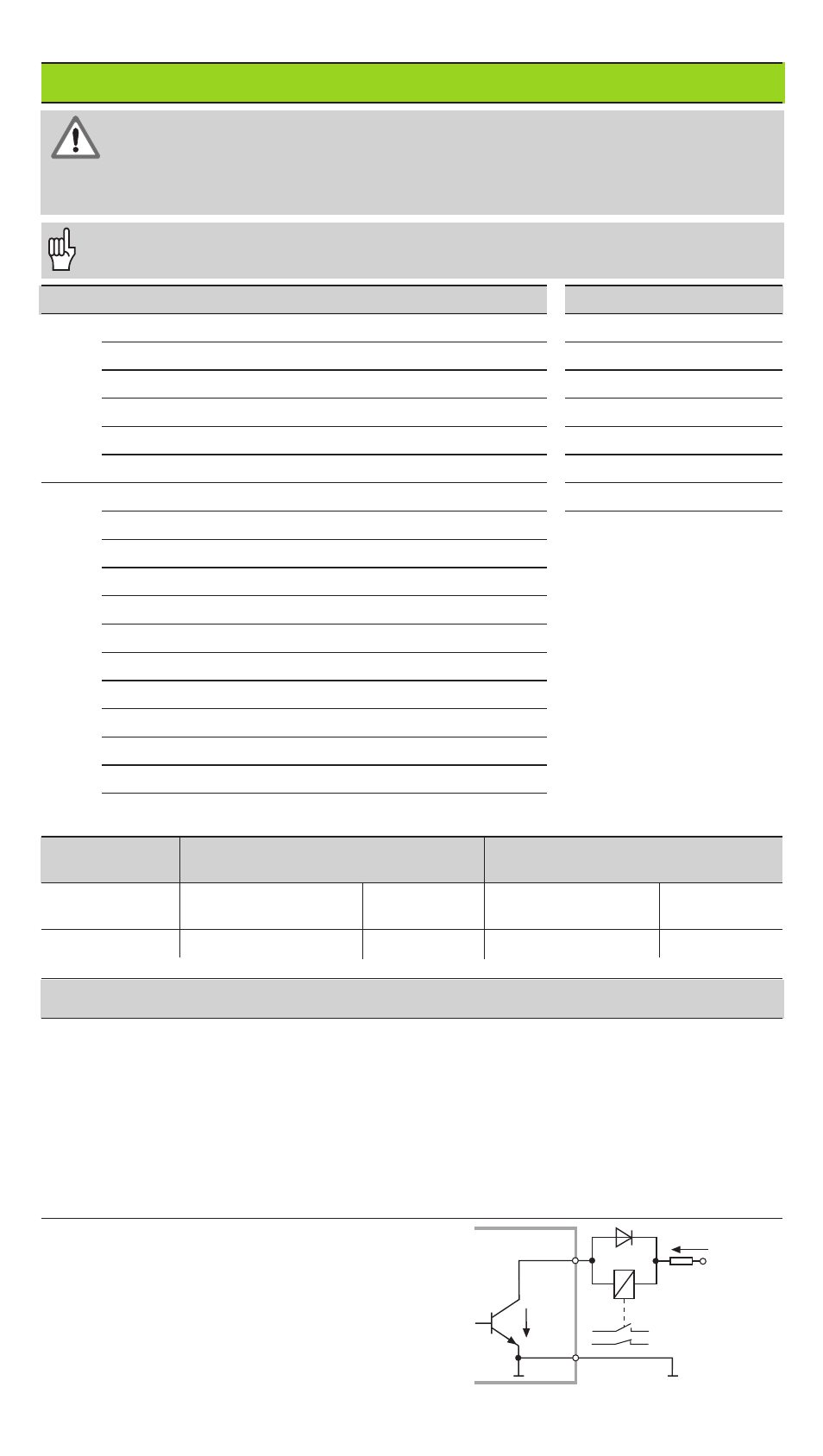
Outputs
Inputs
Use only shielded cable!
Connect the shield to the connector housing.
B
UCE
E
C
Pin 1.10
0 V
+ UB
≤
32 V
I
≤
100 mA
D-Sub Connection EXT (25-pin, male)
Pin
Function
Pin
Function
15
Meas. value
≥
trigger limit A1 (P62)
1
0 V
16
Meas. value
≥
trigger limit A2 (P63)
10
0 V
17
Meas. value < lower sorting limit (P18)
12
Do not assign
18
Meas. value > upper sorting limit (P19)
13
Do not assign
19
Error (see
Error Messages)
11
Vacant
14
Display value is zero
20
Vacant
2
Reset display to zero, clear error message
21
Vacant
3
Preset display to value from P79
25
Cross over reference marks
4
Ignore reference mark signals
5
Start measuring series
6
Remote selection of display val. f. meas. ser.
7
Display minimum value from meas. series
8
Display maximum value from meas. series
9
Display MAX – MIN diff. from meas. series
22
Pulse: output measured value
23
Contact: output measured value
24
Deactivate BCD data output
Signal levels
Low
High
Inputs
–0.5 V
≤
U
≤
0.9 V
I
≤
6 mA
3.9 V
≤
U
≤
15 V
Outputs
U
≤
0.4 V
I
≤
100 mA
U
≤
32 V
I
≤
10 µA
Description of input and output signals
Input signals
• Triggering by make contact against 0 V or
•
Low level over TTL component
• Internal pull-up resistor 1 k
Ω
• Min. pulse duration: t
≥
30 ms, for fast reset/preset: t
≥
30
µ
s
• Min. pulse interval: t
≥
30 ms, for reset/preset: t
≥
1,5 ms;
for fast reset/preset: t
≥
30
µ
s
• Delay for zero reset/preset: fast data output t
d
≤
25 µs;
•
slow data output t
d
≤
2 ms
Output signals
• Open collector outputs,
active Low
• Signal output delay: t
d
≤
8 ms
• Zero crossover signal
minimum duration, trigger
output A1, A2: t
0
≥
180 ms
Note that these times increase if additional
features are active (such as sorting).
Danger to internal components!
Voltage sources for external circuitry must conform to the recommendations in
EN 50 178 for low-voltage electrical separation. Connect inductive loads only
with a quenching diode parallel to the inductance.
Display current meas-
ured value (ACTL):
Inputs 7, 8 and 9 are
not active, or more
than one of these
inputs is active