Auxiliary vga switching, Kvm switching, Figure 3 on – Grass Valley XSwitch Feb 08 2006 User Manual
Page 9
XSWITCH Installation and Operation Manual
9
Major Components
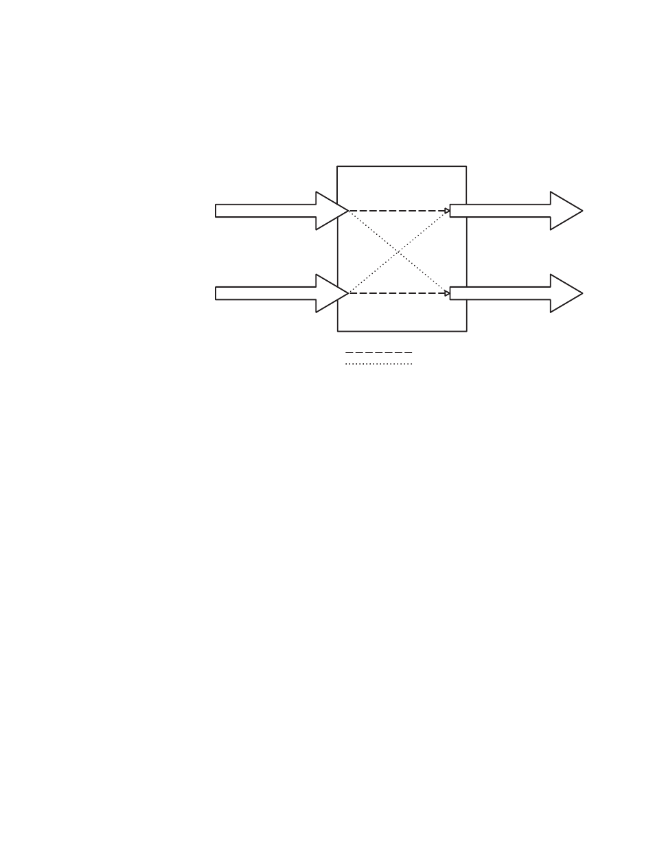
source A is connected to receiving device B and source B is connected to
receiving device A. The actual audio channel switching consumes a
maximum of 50 ms.
Figure 3. Audio XSWITCH Card
Auxiliary VGA Switching
Certain installations may require VGA switching capability beyond that
offered by the KVM Module. An auxiliary VGA switching card is available
for such instances. This card is very similar to the Communication Switch
Card described earlier. Again, the signal paths are switched by passive
relay contact. Signal paths on the open side of the switch are not termi-
nated. It is a Form C type switch with two inputs and one output. The con-
nectors are high density 15 pin D type connectors for VGA interface (socket
inputs, pin outputs). Contact exchange occurs within 6mS maximum,
including settling time.
KVM Switching
The KVM module contains both active and passive switching (
). It is a dual cross-switch that can handle two systems, each com-
prising 2 keyboards, 2 mouse-type pointing devices, and 4 VGA monitors.
The two KVM systems cannot be switched independently. The I/O connec-
tors are high-density 15-pin D-type connectors for VGA interface (socket-
type inputs, plug-type outputs) and socket MINI-DIN connectors for key-
board and mouse interface.
Audio XSwitch
Normal Path
Switched Path
Source B
Source A
Destination B
Destination A
8393_03_r1