Switch cards, Communication signal switching – Grass Valley XSwitch Feb 08 2006 User Manual
Page 7
XSWITCH Installation and Operation Manual
7
Major Components
Switch Cards
The basic XSWITCH configuration is pre-loaded with:
•
1 CPU Card
•
6 Communication Switch Cards
•
2 SDI (Video) Switch Cards
•
2 Audio Switch Cards
•
1 KVM Module
Each switch card design performs a specific signal switching; e.g., Commu-
nications, Video, Audio. All switch cards contain circuitry that communi-
cates over a common bus with the microprocessor on the CPU card. Except
for the KVM module, these circuits are identical.
Communication Signal Switching
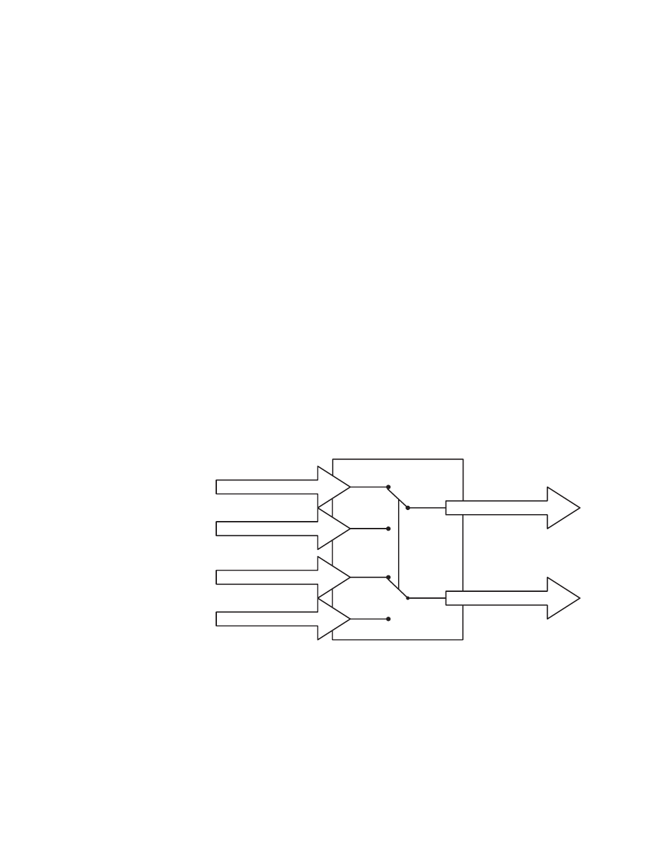
The Comm Switch Card is a passive, relay-based switching device (
) with standard 9-pin, D-type I/O connectors. The input (control
source) connectors are socket type and the output (peripheral) connectors
are pin type. There are no active electronics (semiconductor devices such as
ICs or discrete transistors) in the signal paths.
Figure 1. Serial Data Y Switch
As a passive switching device, the Comm Switch Card does not signifi-
cantly affect or alter the electrical characteristics of the signal paths being
switched. However, signal paths on the open side of the switch are not ter-
minated. This card employs a form C configuration and can switch two sets
of communication ports. The typical topology comprises one peripheral
device and two control systems per set. Both sets are switched simulta-
neously. Due to the passive switching circuitry, the communication signals
Ignite A Out
Ignite B Out
Ignite A Out
Ignite B Out
Device A
Device B
Serial Data "Y" Switch
8393_01_r1