Vertigo xg signal path and rendering processes, Vertigo xg signal path and rendering processes -9 – Grass Valley XG Vertigo Configuration Guide v.5.0 User Manual
Page 20
Vertigo XG Configuration Guide
2-9
Overview of the Vertigo XG’s Hardware
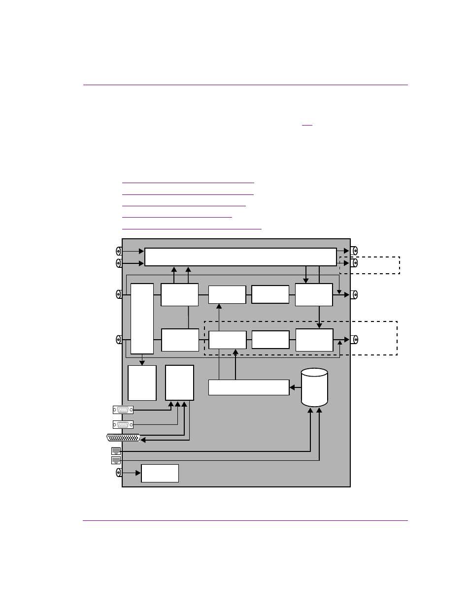
Vertigo XG signal path and rendering processes
The Vertigo XG HD/SD graphics processor block diagram (figure
) demonstrates that the
audio and video signals are brought into the Vertigo XG hardware, exposed to various
processing options, and then rendered for output.
To help you make more informed configuration decisions, the following sections describe
the signal path and processing options that performed by the Vertigo XG hardware and
software drivers.
•
“Video input/output channels” on page 2-10
•
“Audio input/output channels” on page 2-11
•
“Ancillary data processing” on page 2-12
•
“Graphics processing” on page 2-12
•
“Clip Player and media storage” on page 2-13
Figure 2-3. Block diagram of the dual channel Vertigo XG (VX-Vertigo-XG22-e)
Media
Storage
RS-232
Audio Mixer & Processor
Relay Bypass A
SD/HD Channel 1
Input A
AES IN A
REF IN
GigE Media
Import
SD/HD Channel 1
Output A
AES OUT A
Clip Player
Ancillary
Data
GPI-8 I/O
SD/HD Channel 2
Input B
SD/HD Channel 2
Output B
Compositor
Rendering A
DVE & Keyer
Audio
Embedder
Compositor
Virtual
Input
Switch
Genlock
AES IN B
AES OUT B
Relay Bypass B
Processing
Controller
Audio
De-embedder
Audio
De-embedder
Rendering B
DVE & Keyer
(channels 1-16)
(channels 1-16)
(ch. 1-4)
(ch. 5-8)
Audio
Embedder
RS-422
(Optional)
XG-22-e model only
(Optional)
XG-22-e model only