Cabling and control, Cabling, Figure 15 – Grass Valley KayakDD-2 v.6.7.1 User Manual
Page 54: Kayakdd-2 standard cabling, 7 cabling and control, 1 cabling, Kayakdd-2 digital production switcher, Dc power supply 48v (redundancy)
KayakDD-2 Digital Production Switcher
6.7 Cabling
and
Control
6.7.1 Cabling
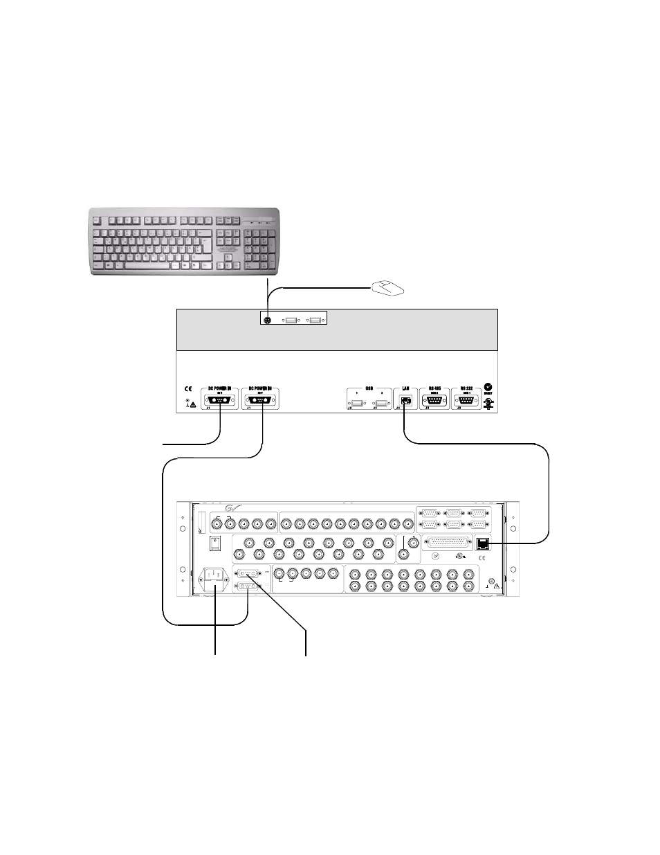
The cabling of a standard KayakDD-2 application is illustrated in figure below.
USB
P/S 2
3
4
Control Panel
Video Processor Frame
AC Power Supply
110-240V
DC Power Supply
48V (Redundancy)
Keyboard
Mouse
Note:
Keyboard and Mouse not
mandatory and not supplied.
CAT5 Crossover Cable
N4067
GPI/O - Tally
LAN
RS 485
INPUT 1-16
REFERENCE
AUX 1-10
AC POWER IN
100 - 240 V
max. 4A
50/60 Hz
DC POWER
IN
J2
J 4
J 5
J 6
J 7
J 8
PGM
CLEAN
PVW
CLEAN-PVW
AUX 1
AUX 2
AUX 3
AUX 4
AUX 5
AUX 6
AUX 7
AUX 8
AUX 9
AUX 10
J 9
J 10
J 11
J 12
J 13
J 14
J 15
J 16
J 17
J 18
Port 1
Port 2
Port 3
Port 4
Port 5
Port 6
J 19
J 20
J 21
J 22
J 24
J 23
J 25
IN 1
IN 2
IN 3
J 26
J 27
J 28
J 29
J 30
J 31
J 32
J 33
J 34
J 35
J 36
J 37
J 38
J 39
J 40
IN 4
IN 5
IN 6
IN 7
IN 8
IN 9
IN 10
IN 11
IN 12
IN 13
IN 14
IN 15
IN 16
J 41
J 42
ANALOG
J 44
J 43
grass valley
48V / 5A max.
KAYAK
2 M/E DIGITAL SWITCHER
R
3S13
Prof. Vid. Equipm.
Listed
J3
OUT
48V / 1,6A
J 45
J 46
J 47
J 48
J 49
J 50
IN 17
J 58
IN 25
J 51
IN 18
J 59
IN 26
J 52
IN 19
J 60
IN 27
J 53
IN 20
J 61
IN 28
J 54
IN 21
J 62
IN 29
J 55
IN 22
J 63
IN 30
J 56
IN 23
J 64
IN 31
J 57
IN 24
J 65
IN 32
INPUT 17-32
This device complies with part 15 of the FCC Rules. Operation is subject to the following two conditions:
(1) This device may not cause harmful interference, and
(2) this device must accept any interference received, including interference that may cause undesired operation.
DD-2
T
Y
P
E
P
A
R
T
N
O
.
S
E
R
.
N
O
.
K
A
Y
A
K
D
D
-2
0
2
1
2
3
9
0
0
1
0
1
0
0
g
ra
s
s
v
a
lle
y
P/P
PGM
CLEAN
PVW
CLEAN-PVW
M/E
Caution: For continued protection against risk
of fire, repplace only with same type and rating of fuse.
2*T6,3A /H
250V
J1
DC Power Supply
48V (Redundancy)
Figure 15
KayakDD-2 Standard Cabling
Planning and Installation Manual
53