Chapter 3 servicing the k2 lx0 raid – Grass Valley K2 Lx0 RAID Storage User Manual
Page 36
36
K2 Lx0 RAID Instruction Manual
July 31, 2008
Chapter 3 Servicing the K2 Lx0 RAID
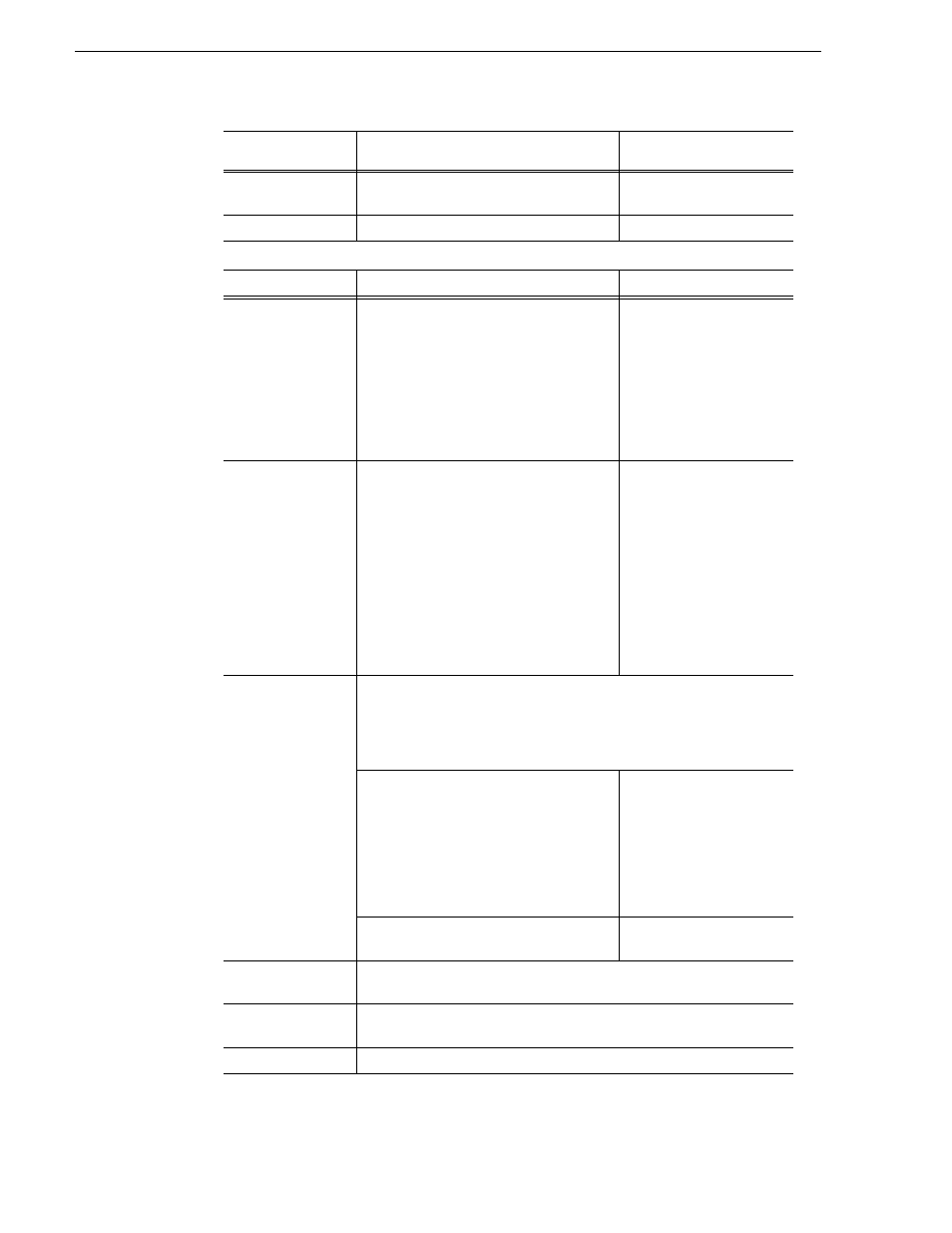
On
Blinking
Waiting for disk enclosure
power-on
Off
Off
Powered off
Indicator
Description
Backup LED (6)
Blinks orange light to indicate the battery
backup state
Blinks if the controller has
lost power, was improperly
shut down, or faulted, with
data in its cache that has not
been written to disk. These
conditions need to be
rectified before the backup
battery discharges (about 24
hours).
HP connector (7)
Connects the disk array unit to a host.
Without an expansion port, there are two
ports per controller. With an expansion port,
there are six ports per controller.
On the left is the Access LED, which shows
the state of I/O processing. On the right is
the Link LED, which shows the state of the
FC link.
Locations and port numbers
HP5 HP4 HP3 HP2
HP1
HP0
Both LEDs blinking in a
one-second cycle shows the
port if offline
Both LEDs blinking
quickly (500ms cycle)
shows the shutdown
sequence is in progress.
Any other simultaneous
blinking shows that the port
setting is not correct.
SAS connector (8)
Connects the K2 Lx0 RAID to expansion chassis. Two connectors per
controller.
Locations and port numbers
DP1 DP0
(Optional) DP1 — only used with the Level 30 and Level 30R RAID
Link LED (green)
Illuminates to indicate that
the link-up is being
executed on the Expansion
chassis.
Off state indicates that
the link-down is being
executed on the Expansion
chassis
Fault LED (orange)
Illuminates to indicate an
error.
Extended BBU
connector (9)
Not used.
Modem connector
(10)
Not used.
Ejector (11)
Used to install or remove the controller.
Ready LED (4)
(green)
Fault LED (5)
(orange)
Meaning