Cable k2 summit production client, Cable k2 solo media server, Cabling systems – Grass Valley K2 Dyno Installation v.1.6 User Manual
Page 16: Power cord
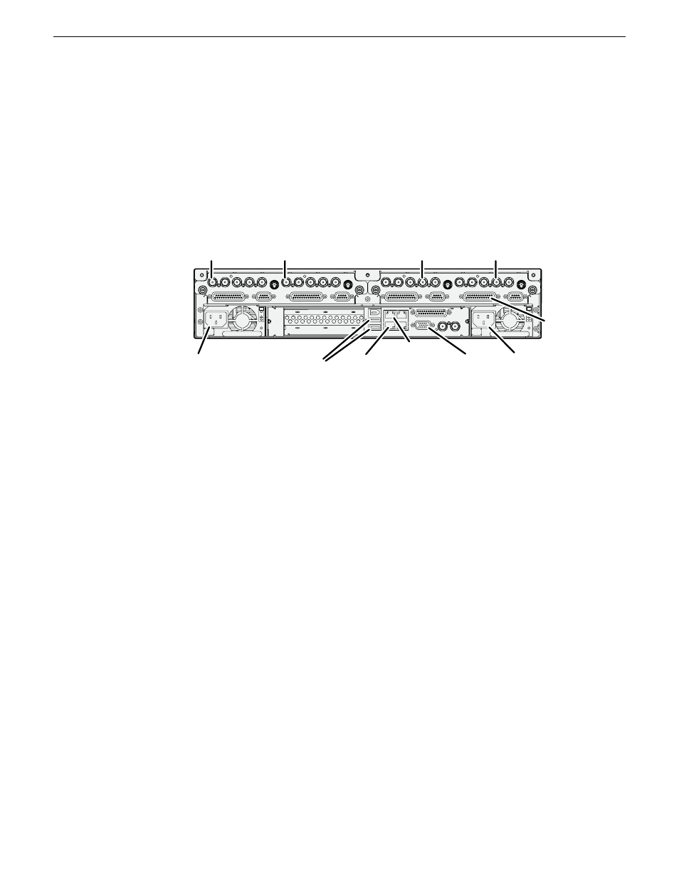
Cable K2 Summit Production Client
1. If desired, mount the K2 Summit Client in an equipment rack. Refer to the K2
System Guide for rack mount procedures.
2. Make cable connections. Connections for a typical system are illustrated.
C1
C2 C3
C4
!
OK
~AC
!
OK
~AC
SDI IN
1
SDI OUT
1
SDI OUT2
LTC I/O
AESAUDI
O
RS422
SDI OUT1 SDI OUT
2
USB/1394
100BT/1000BT
GPI
VGA
REF. LOOP THROUG
H
AESAUDI
O
RS422
LTC I/O
SDI IN
2
SDI IN
3
SDI IN
1
SDI IN
2
SDI IN
3
SDI IN
1
SDI OUT
1
SDI OUT2
LTC I/O
AESAUDI
O
RS422
SDI OUT1 SDI OUT2
AESAUDI
O
RS422
LTC I/O
SDI IN
2
SDI IN
3
SDI IN
1
SDI IN
2
SDI IN
3
Power
cord
Power
cord
AES
audio
Keyboard
and mouse
VGA
monitor
Channels (C1, C2, C3, C4) are bi-directional
Ethernet
control
connection
Optional:
Ethernet
media
(FTP)
connection
Use C1 as
record channel.
Connect SDI in
Use C2 as
record channel.
Connect SDI in
Use C3 as
play channel.
Connect SDI out
Use C4 as
play channel.
Connect SDI out
Each channel can be both an input (record channel) and an output (play channel).
For the typical system, C1 and C2 are record channels and C3 and C4 are play
channels.
The control connection between the K2 Summit Client and the K2 Dyno
Controller can be via direct connect cable or via an Ethernet switch. Control
connections must be on the same network (subnet).
For complete cabling instructions, refer to the K2 System Guide. If using ChannelFlex
Suite features, refer to the K2 AppCenter User Manual.
Cable K2 Solo Media Server
1. If desired, mount the K2 Solo Media Server in an equipment rack. Refer to the K2
Solo Media Server Accessories Installation Instructions for rack mount procedures.
2. Make cable connections. Connections for a typical system are illustrated.
16
K2 Dyno Controller Installation Manual
13 April 2010
Cabling systems