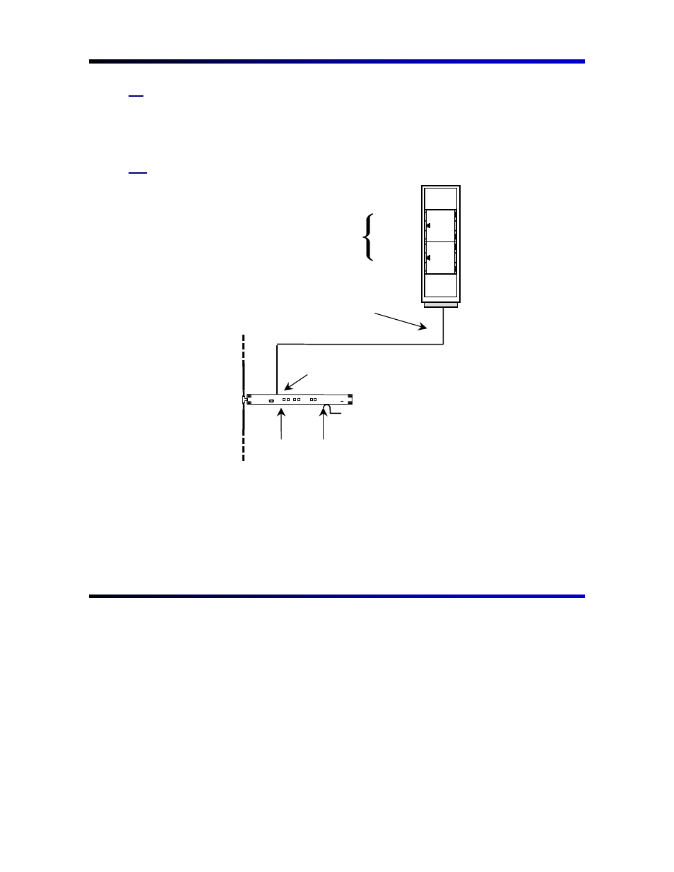
Figure 2. control panel installation – Grass Valley Jupiter Control System User Manual
Page 5
3
G
G
e
e
t
t
t
t
i
i
n
n
g
g
S
S
t
t
a
a
r
r
t
t
e
e
d
d
w
w
i
i
t
t
h
h
H
H
a
a
r
r
d
d
w
w
a
a
r
r
e
e
To the customer:
Someone once said that a picture is worth a thousand words. Concerning the Jupiter
set up, this statement is certainly true. The diagrams below should make the
hardware set up quite simple.
Figure 1. Connection to Philips/Thomson routing switchers
VM 3000
Control
Processor
LAN
House sync required for
vertical interval switching.
House T/C
(Optional)
Binary protocol
Crosspoint bus port
15-pin CC 2010 Matrix (crosspoint bus) data cable
For jumper and
switch setting
information, refer
to the hardware
manual supplied
with the switcher.
SDR 400
Mars
Venus
Trinix
See also other documents in the category Grass Valley Equipment:
- LDK 5302 (24 pages)
- SFP Optical Converters (18 pages)
- 2000GEN (22 pages)
- 2011RDA (28 pages)
- 2010RDA-16 (28 pages)
- 2000NET v3.2.2 (72 pages)
- 2000NET v3.1 (68 pages)
- 2020DAC D-To-A (30 pages)
- 2000NET v4.0.0 (92 pages)
- 2020ADC A-To-D (32 pages)
- 2030RDA (36 pages)
- 2031RDA-SM (38 pages)
- 2041EDA (20 pages)
- 2040RDA (24 pages)
- 2041RDA (24 pages)
- 2042EDA (26 pages)
- 2090MDC (30 pages)
- 2040RDA-FR (52 pages)
- LDK 4021 (22 pages)
- 3DX-3901 (38 pages)
- LDK 4420 (82 pages)
- LDK 5307 (40 pages)
- Maestro Master Control Installation v.1.5.1 (455 pages)
- Maestro Master Control Installation v.1.5.1 (428 pages)
- 7600REF Installation (16 pages)
- 7600REF (84 pages)
- 8900FSS (18 pages)
- 8900GEN-SM (50 pages)
- 8900NET v.4.3.0 (108 pages)
- Safety Summary (17 pages)
- 8900NET v.4.0.0 (94 pages)
- 8906 (34 pages)
- 8911 (16 pages)
- 8900NET v.3.2.2 (78 pages)
- 8914 (18 pages)
- 8912RDA-D (20 pages)
- 8916 (26 pages)
- 8910ADA-SR (58 pages)
- 8920ADC v.2.0 (28 pages)
- 8920ADC v.2.0.1A (40 pages)
- 8920DAC (28 pages)
- 8920DMX (30 pages)
- 8920ADT (36 pages)
- 8920MUX (50 pages)
- 8921ADT (58 pages)