Cabling and rear panel connections – Grass Valley iTX Playout Appliance v.2.3 User Manual
Page 23
11
iTX Playout Appliance
Installation & Quick Start Guide
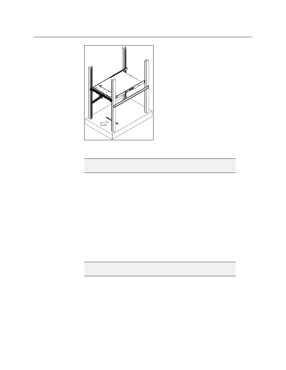
Fig. 2-4: Mounting the iTX Playout Appliance’s chassis into a rack
WARNING
Slide/rail mounted equipment is not to be used as a shelf or a workspace.
5 To completely remove the chassis from the rack, you must release the locking tabs on
both sides of the chassis.
6 Re-attach the faceplate by aligning and pushing the faceplate towards the iTX Playout
Appliance’s chassis.
Cabling and rear panel connections
Once the iTX Playout Appliance’s chassis is securely mounted in an equipment rack, you can
make the required connections to the server’s rear connectors (Figure 2-5).
Make the following connections to the rear panel of the iTX Playout Appliance:
1 Connect the two (2) AC power cables to the power supply sockets on the rear panel of
the iTX Playout Appliance’s chassis.
IMPORTANT
DO NOT plug the power cables into AC power sockets yet.
2 Connect the keyboard and mouse cables.
3 Connect the video monitor’s cable to the VGA connector (dual channel model) or to the
DVI connector (single channel model). Power on the monitor.
4 Connect the license dongle to the iTX Playout Appliance’s USB1 port. The license
dongle authenticates the iTX software and allows you to use the software once the
license is registered in the iTX system.
5 Connect the iTX Playout Appliance device to the Local Area Network (LAN) by
connecting an Ethernet cable to the LAN1 connector.