Alarm status – Grass Valley iControl Solo User Manual
Page 20
16
Using iControl Solo
Alarm Status
3
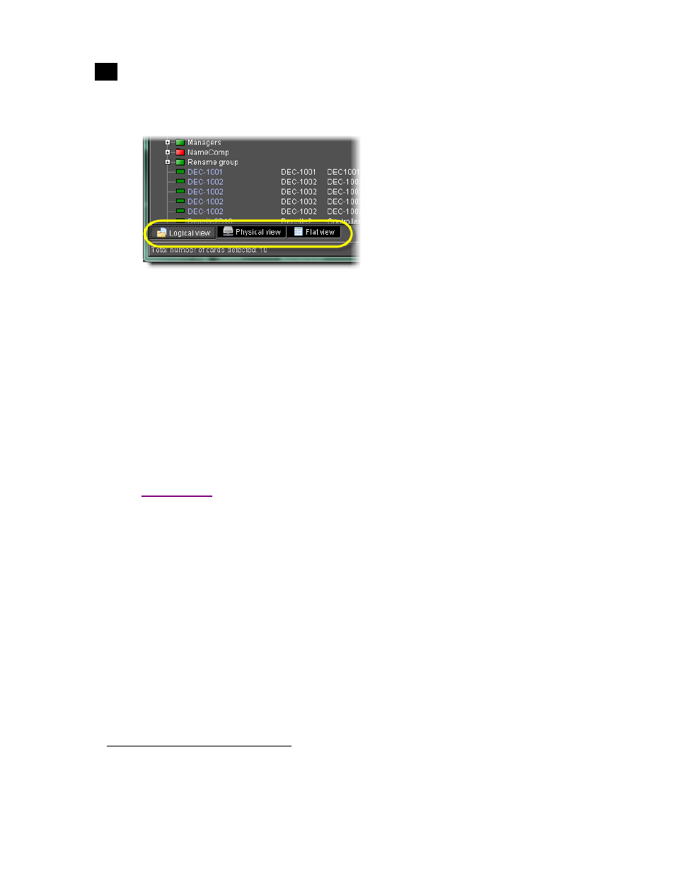
Three views are available by clicking tabs at the bottom of the Navigator window.
Navigator tabs (circled)
• Logical view displays all active services and devices interfaced with iControl Solo. The devices and
services may be organized into groups. Groups and their contents are arranged in alphabetical order.
Ungrouped items are displayed at the end of the list. Empty slots are not shown, unless they are in the
Reference Configuration (see
"Reference Configuration", on page 17
• Physical view arranges the devices relative to their physical connections and network location. All
frame slots are shown. Empty slots show up as “Empty,” unless the card is designated as “In Ref.
Configuration,” in which case it will show up as before, but with the description “missing from slot.”
Devices are sorted by the name you typed when you added a Densité Communicator service, and by the
number of the serial port where an Imaging frame is connected.
• Flat view shows all devices in alphabetical order without any grouping.
Alarm Status
The current status of an alarm determines the color of any on-screen object associated with that alarm: the
LED-like icon to the left of a device or service label, an enclosing folder, etc. Each possible alarm status is
represented by a color. Alarm statuses are dynamically updated.
iControl Solo implements an industry standard
1
color code definition for all alarms. The following table
describes the color scheme used by iControl Solo to display alarm statuses, and how they map to the
ITU-TX.733 Recommendation:
1. Default alarm severities in iControl Solo are compliant with the intent of ITU-T Recommendation X.733, Information
Technology – Open Systems Interconnection – Systems Management – Part 4: Alarm Reporting Function