Appendix d: pin-out diagrams, Page 17 – Grass Valley 3-CCD ANALOG CameraMan Rev.B User Manual
Page 20
Page 17
Appendices
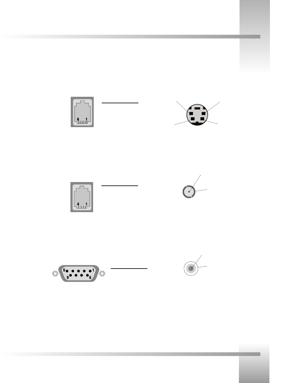
Appendix D: Pin-Out Diagrams
You’ll find the following pinout connections on the back of your connector box on the back of your CameraMan. These diagrams
are for your reference.
RS-485
Four position
Modular Handset
PVI COM
RJ-11
Pin
Signal
1
12v
2
12v
3
Ground
4
Signal A
5
Signal B
6
Ground
RS-232
9-pin Female D-9 Sub
Pin
Signal
2
Transmit
3
Receive
5
Ground
1,4,6-9 Not Used
Pin
Signal
1
Ground
2
Signal A
3
Signal B
4
Ground
S-Video Connector
BNC Connector
+ 18v DC
Ground
Video (1Vpp)
C
Y
Y Ground
C Ground
Ground
5.5mm DC Power
Connector
See also other documents in the category Grass Valley Equipment:
- LDK 5302 (24 pages)
- SFP Optical Converters (18 pages)
- 2000GEN (22 pages)
- 2011RDA (28 pages)
- 2010RDA-16 (28 pages)
- 2000NET v3.2.2 (72 pages)
- 2000NET v3.1 (68 pages)
- 2020DAC D-To-A (30 pages)
- 2000NET v4.0.0 (92 pages)
- 2020ADC A-To-D (32 pages)
- 2030RDA (36 pages)
- 2031RDA-SM (38 pages)
- 2041EDA (20 pages)
- 2040RDA (24 pages)
- 2041RDA (24 pages)
- 2042EDA (26 pages)
- 2090MDC (30 pages)
- 2040RDA-FR (52 pages)
- LDK 4021 (22 pages)
- 3DX-3901 (38 pages)
- LDK 4420 (82 pages)
- LDK 5307 (40 pages)
- Maestro Master Control Installation v.1.5.1 (455 pages)
- Maestro Master Control Installation v.1.5.1 (428 pages)
- 7600REF Installation (16 pages)
- 7600REF (84 pages)
- 8900FSS (18 pages)
- 8900GEN-SM (50 pages)
- 8900NET v.4.3.0 (108 pages)
- Safety Summary (17 pages)
- 8900NET v.4.0.0 (94 pages)
- 8906 (34 pages)
- 8911 (16 pages)
- 8900NET v.3.2.2 (78 pages)
- 8914 (18 pages)
- 8912RDA-D (20 pages)
- 8916 (26 pages)
- 8910ADA-SR (58 pages)
- 8920ADC v.2.0 (28 pages)
- 8920ADC v.2.0.1A (40 pages)
- 8920DAC (28 pages)
- 8920DMX (30 pages)
- 8920ADT (36 pages)
- 8920MUX (50 pages)
- 8921ADT (58 pages)