Appendix b: multi-camera applications – Grass Valley 3-CCD ANALOG CameraMan Rev.B User Manual
Page 18
Page 15
Appendices
Appendix B: Multi-Camera Applications
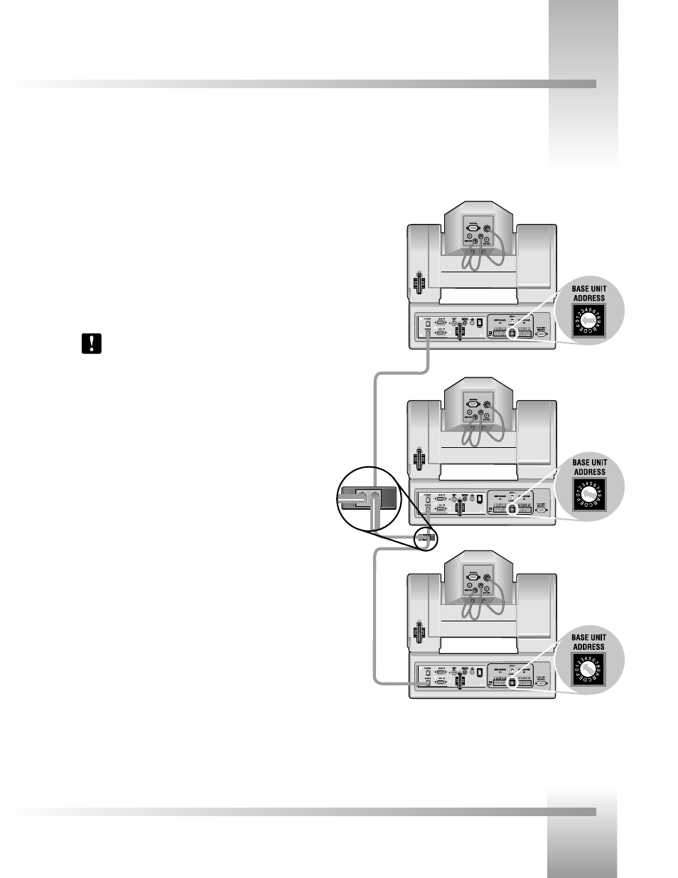
If your application requires that you have more than one CameraMan, you will need to set them up in a “daisy-chain” network
configuration by following these steps:
1. Connect the cameras together by plugging the supplied T-connector into the
RS-485 port on the back of the camera.
2. Connect each camera using a 4-conductor cable, with 4-position modular handset plugs
wired "straight-through":
Pin 1...........Pin 1
Pin 2...........Pin 2
Pin 3...........Pin 3
Pin 4...........Pin 4
Note: Do NOT use a standard phone cable, as these are wired differently and
may cause damage.
3. Using the BASE UNIT ADDRESS rotary switch, which is located on the back of the
Camera, configure each camera with a unique Base Unit Address.
(i.e.: Camera One would be set with address 0, Camera Two would be set with
address 1, and so on)
4. In order to control each camera with your Camera Control Keypad, the rotary switch
inside the keypad battery compartment must match the lowest Base Unit
Address in your system. For example, if the Base Unit Address switches are
set according to the illustration to the right, the rotary switch inside the
keypad should be set to zero. The Camera Control Keypad can control up
to three cameras.
Camera One
Camera Two
Connector T
Camera Three