Grass Valley ADX-1901 User Manual
Page 11
GUIDE TO INSTALLATION AND OPERATION
ADX-1901 | 7
See
for instructions on installing and removing the SFP interface module, and for plugging and unplugging
the LC-terminated fibers.
The SFP modules supported by the ADX-1901 are:
SFP Modules
Description
SFP-T-S13-LC
Single fiber Tx (output) module at 1310 nm with LC/PC connector
SFP-TT-S13S13-LC
Dual fiber Tx (output) module at 1310 nm with LC/PC connector
SFP-RT-S13-LC
Dual fiber Rx (input) and Tx (output) module at 1310 nm with LC/PC connectors
SFP-R-LC
Single fiber Rx (input) module with LC/PC connector
SFP-RT-W13-LC
Single fiber Rx/Tx module at 1310 nm with WDM, LC/PC connector
SFP-RT-W15-LC
Single fiber Rx/Tx module at 1550 nm with WDM, LC/PC connector
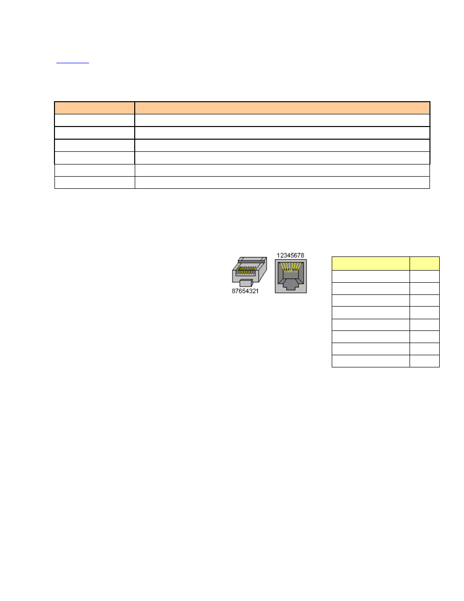
RS-422 / GPI / LTC – Metadata Output, GPI Outputs and Timecode Output
RS-422, GPI and LTC signals are carried on an RJ-45 connector, with the pinout as shown in the table:
Note:
A GPI output is open when inactive and connected to ground when active.
Function
Pin #
NC
1
NC
2
RS422-TX-1
3
LTC OUTPUT
4
GPIO USER2 OUTPUT
5
RS422-TX-0
6
GPIO USER1 OUTPUT
7
GND
8