3 functional diagram, 2 installation, 1 unpacking – Grass Valley ADC-1722 User Manual
Page 6: 2 installation in the densité frame
GUIDE TO INSTALLATION AND OPERATION
6/22 | ADC-1722
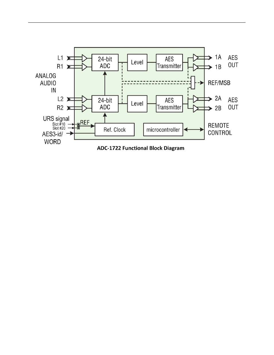
1.3 Functional Diagram
2 Installation
2.1 Unpacking
Make sure the following items have been shipped with your ADC-1722. If any of the following items are
missing, contact your distributor or Miranda Technologies Inc.
• ADC-1722 Dual analog audio to AES converter
• ADC-1722-DRP-75 or ADC-1722-DRP-110 Dual Rear Panel, or ADC-1722-SRP-75 or ADC-1722-SRP-110
Single Rear Panel (see figure)
2.2 Installation in the Densité frame
The ADC-1722 and its associated rear connector panel must be mounted in a DENSITÉ frame. It is not
necessary to switch off the frame’s power when installing or removing the panel. See the DENSITÉ Frame
manual for detailed instructions for installing cards and their associated rear panels.
When a double–width rear panel is used, the module must be installed in the right-most of the two slots
associated with the rear panel in order to mate with the rear-panel connectors. If it is placed in the wrong slot,
the front panel LED will flash red. Move the card to other slot for correct operation. No damage will result to
the card should this occur.
If a card is placed in the wrong slot, its front panel LED will flash red. Move the card to other slot for correct
operation. No damage will result to the card should this occur.
Attention:
For cards with an Assy# 0696-1200-2xx only – if a reference card is installed in the DENSITÉ frame, e.g. a
REF-1701 in slot #20 or a REF-1801 in slot #10, you have to set the JP1 jumper accordingly. Please refer to
the silkscreen on the card for the jumper position. This selection is automatic with an Assy# starting at 0696-
1200-400.