Grass Valley ADC-1722 User Manual
Page 14
GUIDE TO INSTALLATION AND OPERATION
14/22 | ADC-1722
The table below lists the various status icons that can appear, and how they are to be interpreted.
• In cases where there is more than one possible interpretation, read the error message in the iControl
window to see which applies.
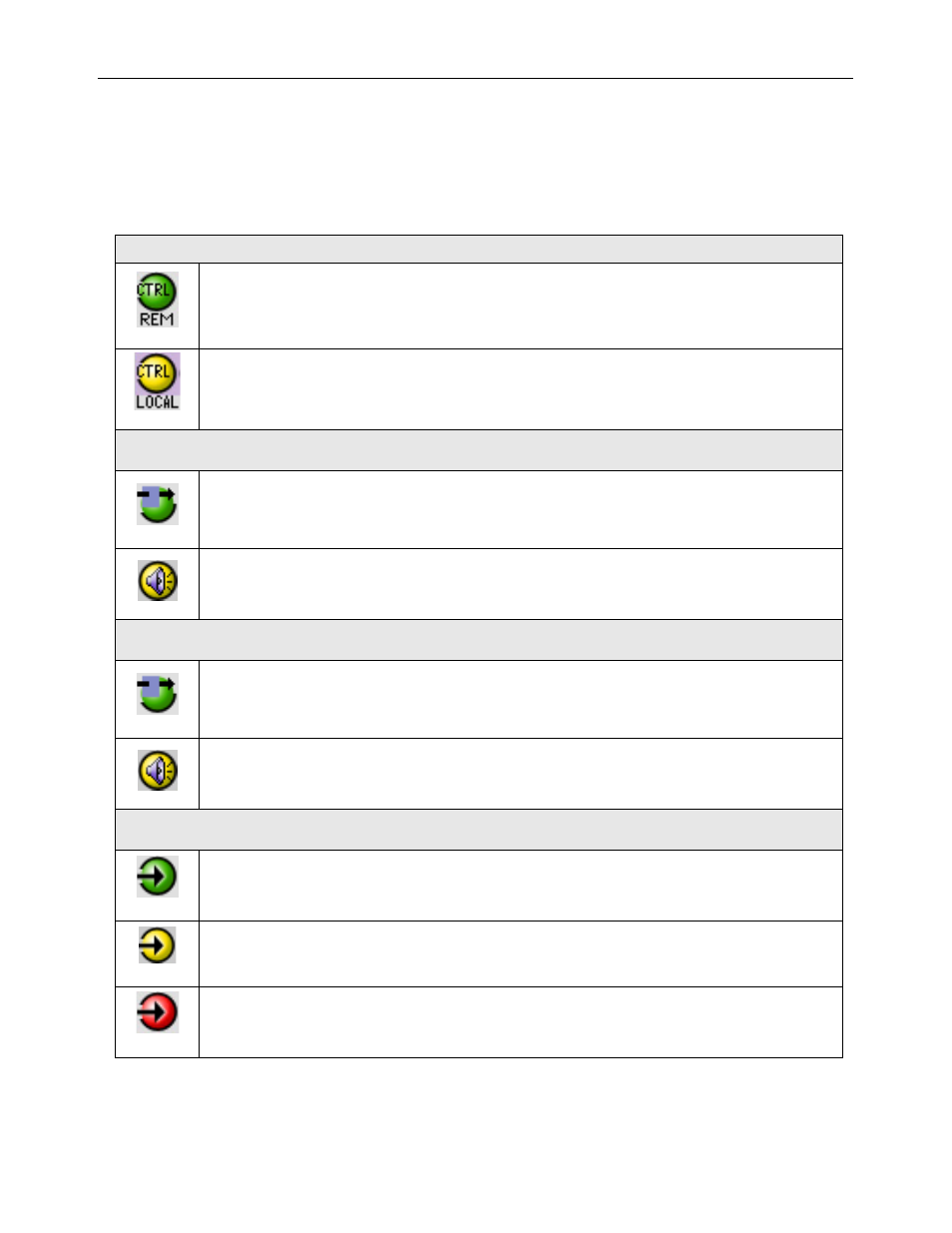
Table – iControl Status Icon interpretation
Icon #1 – Manual Card Configuration
(green)
Remote card control activated. The iControl interface can be used to operate the card
(yellow)
Local card control active, The card is being controlled using the Densité frame control
panel, as described in section 3.3. Any changes made using the iControl interface will have
no effect on the card.
Icon #2 – Audio Test Ch 1
(green)
Ch 1 Test OFF
(yellow)
Ch 1 Test ON – audio test tones enabled (see Sect.3.4.1)
Icon #3 – Audio Test Ch 2
(green)
Ch 2 Test OFF
(yellow)
Ch 2 Test ON – audio test tones enabled (see Sect.3.4.1)
Icon #4 – Input 1 status
(green)
Signal detected and valid.
(yellow)
Signal absent (Left and Right reported individually)
(red)
No rear
Reference mismatch