1 the levels panel, 2 the input panel – Grass Valley ADC-1722 User Manual
Page 16
GUIDE TO INSTALLATION AND OPERATION
16/22 | ADC-1722
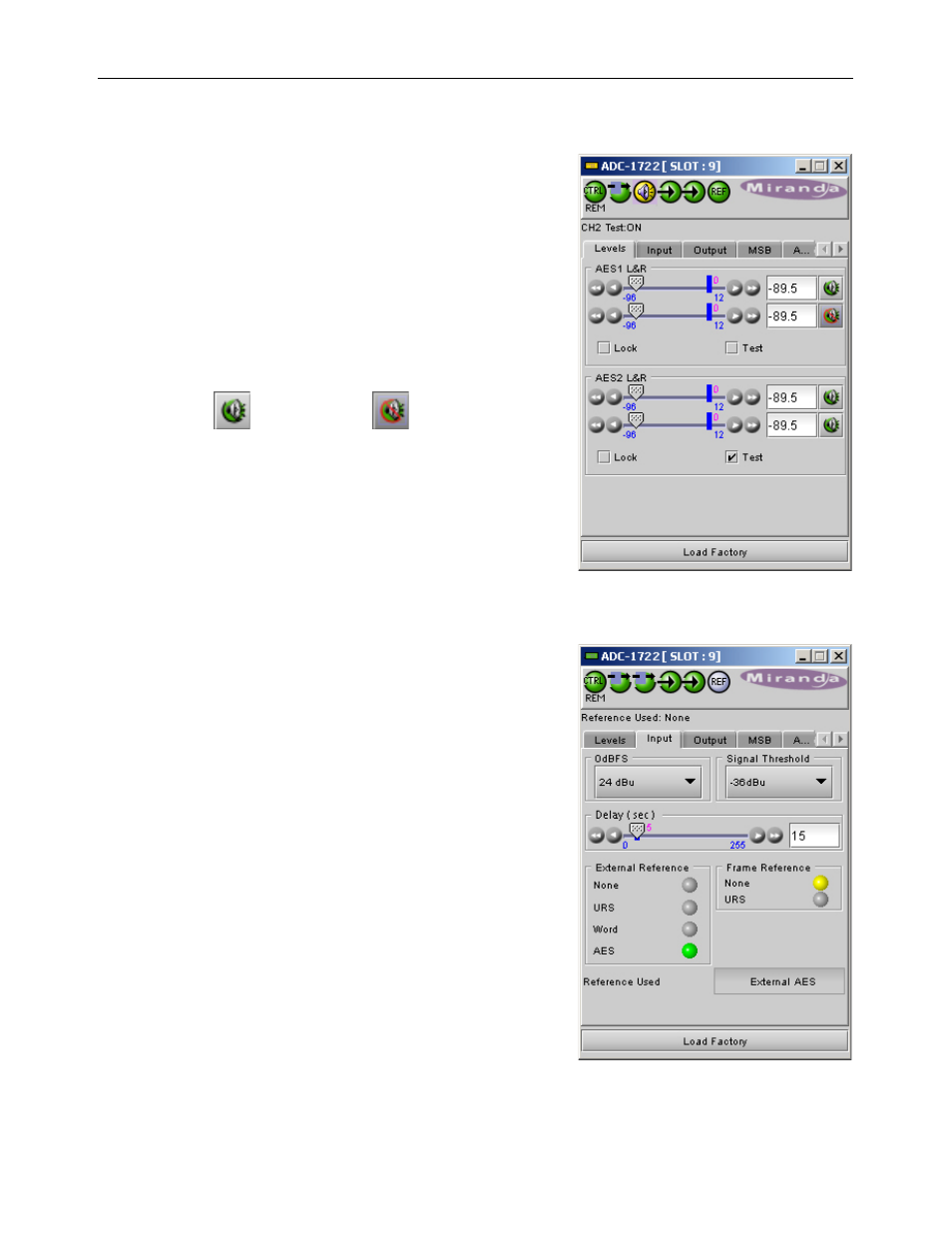
3.4.1 The Levels panel
This panel provides control of the four analog inputs of the ADC-
1722. Each input has identical controls, as follows:
Level – 2 sliders, Left (on top) and Right (below)
Click and drag the slider until the desired value appears in the data
box, or type the desired value into the data box. Use the arrow
icons to move the slider if convenient.
• Range: -96 to +12 dB
Mute – the button to the right of the data box is the MUTE button.
Click it to mute the channel. The icon on the button shows the
status:
Mute OFF:
Mute ON:
Lock – Click in the box to select the Lock mode
The two sliders for this output are locked together, and any value
set on one will automatically apply to the other
Test – the input signals will be replaced by internally generated
test tones.
3.4.2 The Input panel
0 dBFS – use the pulldown to select the analog input signal level
(in dBu) that will be converted to 0 dBFS in the AES digital signal.
• Range: 0 to +24 dBu, 1 dB steps
Signal threshold – use the pulldown to set the level that will be
considered as “signal absent” when triggering card alarms
• Range: -48, -42, -36, -30, -24 dBu
Delay – use the slider or type in the data box to set the period of
time during which the signal must be continuously detected as
“absent” before alarms are triggered.
• Range: 0 to 255 seconds
External Reference – the icons indicate the type of external
reference that is available at the rear panel, if any (URS is only
available with the AMX-1101-DRP rear).
Frame Reference – the icons indicate whether a URS reference is
available in the Densité frame
• Requires a REF-1701 card or a REF-1801 card
• NB must also set the correct position of jumper JP1 to select
between the REF card type if the ADC card has Assy# 0696-1200-2xx.