Functional description, Input and output processing, Microprocessor and input selector – Grass Valley 2040RDA User Manual
Page 22
22
2040RDA — Instruction Manual
Functional Description
Functional Description
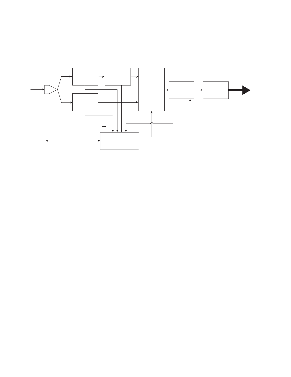
A block diagram of the 2040RDA is shown in
Figure 13. 2040RDA Block Diagram
Input and Output Processing
The input section has a parallel input path from the passive rear input
module for SD (standard definition) and HD (high definition) signal equal-
izing and reclocking. The input section can also bypass the signal through
the HD EQ and HD Reclocker directly to the output amplifiers. The output
amplifiers drive eight equal-phase outputs on the passive rear module
(BNCs J2 – J9).
Microprocessor and Input Selector
The primary purpose of the microprocessor is to provide remote control
and monitoring capability for the 2040RDA. It receives signal present,
signal lock, and speed detection signals from the equalizer and reclocker
circuits. Using this information, local jumper settings, and remote control
commands, the microprocessor selects the internal signal path and gives
feedback through the LEDs and remote control bus.
SD EQ
HD EQ
Microcontroller
Remote control/monitoring
Signal path selection
Bypass
Signal present, locked, speed signals
SD
RECLOCKER
INPUT
AMPLIFIER
SERIAL DIGITAL
INPUT
INPUT
SELECTOR
HD
RECLOCKER
OUTPUT
DRIVERS
8 SERIAL DIGITAL
OUTPUTS
8026_02r1