Power up, Operation indicator leds – Grass Valley 2040RDA User Manual
Page 13
2040RDA — Instruction Manual
13
Power Up
Power Up
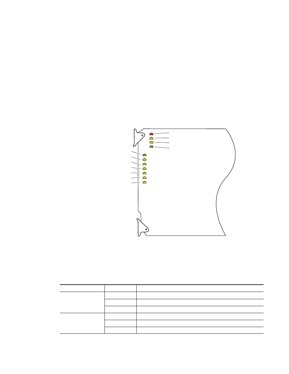
The front LED indicators are illustrated in
. Upon power-up, the
green PWR LED should light and the yellow CONF LED should illuminate
for the duration of module initialization.
Operation Indicator LEDs
With factory default configuration and a valid input signal connected, the
green PWR LED, the green Signal present LED and the detected signal data
rate LED should be on. Refer to
to see a complete list of
possible operating conditions and the resulting indicator status.
Figure 5. LEDs and Configuration Switches
A red FAULT LED indicates an error situation and, when noted with the
other indicator LEDs, can indicate a specific problem area.
describes
signal output and LED indications for the various input/reference combi-
nations and user settings.
Table 1. Indicator LEDs and Conditions Indicated
LED
Indication
Condition
Off
Normal operation
FAULT (red)
On continuously
Module has detected internal fault
Long flash
Configuration problems, check inputs and settings
COMM (yellow)
Off
No activity on frame communication bus
Long flash
Location Command received by the module from a remote control system
Short flash
Activity present on the frame communication bus
8026_01
FAULT (red)
COMM (yellow)
CONF (yellow)
PWR (green)
Signal present (green)
Reclock (yellow)
143 Mb (yellow)
177 Mb (yellow)
270 Mb (yellow)
360 Mb (yellow)
1.5 Gb (yellow)