Configuration – Grass Valley 2040RDA User Manual
Page 14
14
2040RDA — Instruction Manual
Configuration
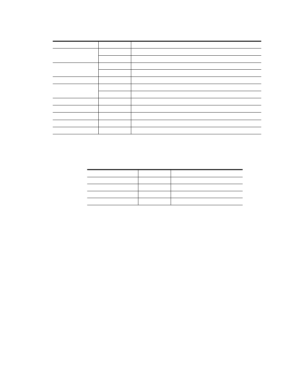
provides the various output conditions possible for a given input
and module setting.
Configuration
The 2040RDA can be configured locally using on-board jumpers or
remotely using the 2000NET network interface.
The following parameter options can be set on the 2040RDA module:
•
Remote control and monitoring lockout,
•
Automatic reclocking mode,
•
Bypass mode (disabled reclocking), and
•
Manual input signal selection mode (remote only).
CONF (yellow)
Off
Module is in normal operating mode
On continuously
Module is initializing, changing operating modes or updating firmware
PWR (green)
Off
No power to module or module’s DC/DC converter failed
On continuously
Normal operation, module is powered
Signal Present (green)
On
Input carrier signal detected
Bypass (yellow)
Off
Reclocking enabled and auto-rate detection mode is active
On
Bypass mode, input signal will not be reclocked
143 Mb (yellow)
On
Input signal is reclocked at 143 Mbps rate
177 Mb (yellow)
On
Input signal is reclocked at 177 Mbps rate
270 Mb (yellow)
On
Input signal is reclocked at 270 Mbps rate
360 Mb (yellow)
On
Input signal is reclocked at 360 Mbps rate
1.5 Gb (yellow)
On
Input signal is reclocked at 1.5 Gbps rate
Table 2. Possible Output Conditions
Input
Setting
Output Condition
Standard Definition SDI video
Auto or Bypass
Standard Definition SDI video
High Definition SDI video
Auto or Bypass
High Definition SDI video
Other carrier
Auto or Bypass
Other carrier
No signal or over EQ range
All modes
Muted
Table 1. Indicator LEDs and Conditions Indicated - (continued)
LED
Indication
Condition