Installation, Local onboard module configuration – Grass Valley 2010RDA-16 User Manual
Page 8
8
2010RDA-16 Instruction Manual
Installation
Installation
Installation of the 2010RDA-16 module is a process of:
•
Configuring the module for Single or Dual operation with an on-board
jumper, JP5,
•
Placing the passive rear module in a rear frame slot,
•
Placing the media module in the corresponding front slot, and
•
Cabling and terminating signal ports.
The 2010RDA-16 module can be plugged in and removed from a Kameleon
2000 Series frame with power on. When power is applied to the module,
LED indicators reflect the initialization process (see
Local Onboard Module Configuration
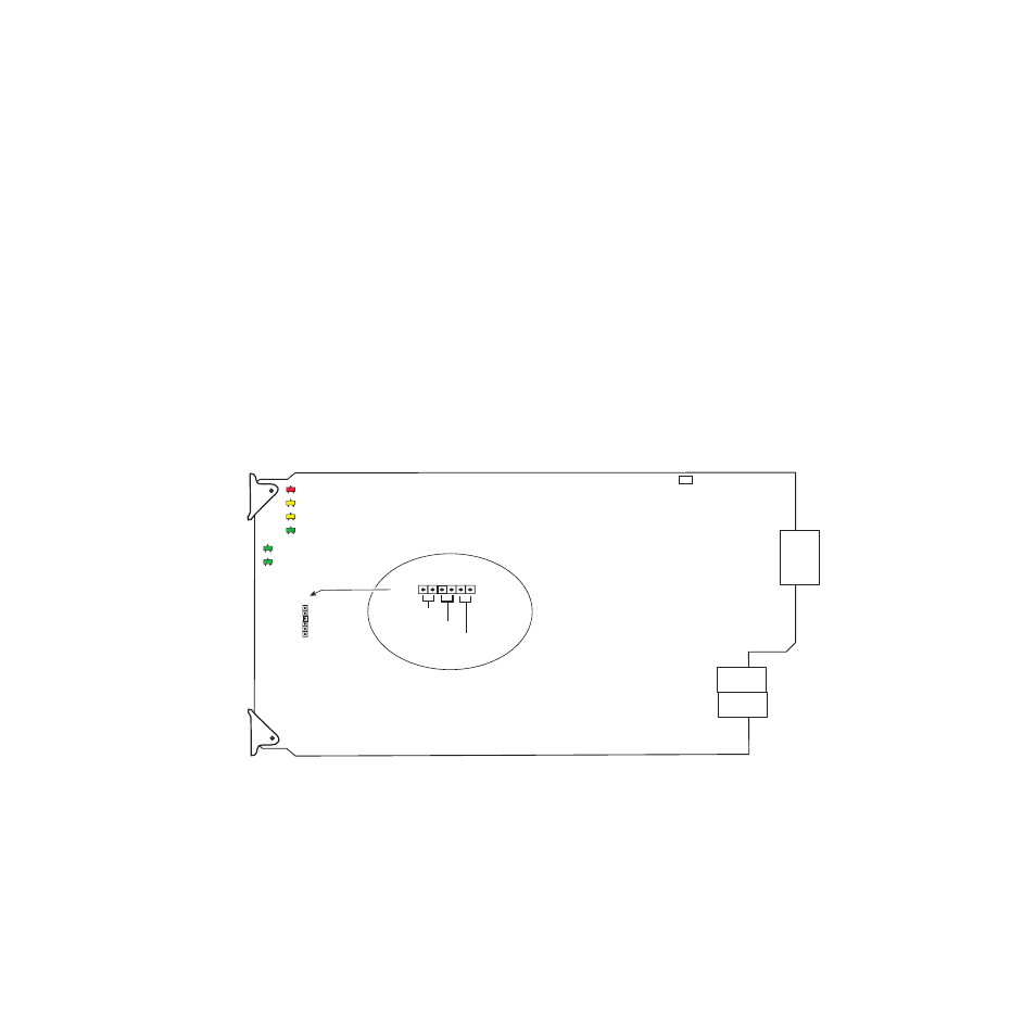
The 2010RDA-16 module is configured locally for Single or Dual operation
using the jumper shown in
Figure 1. Module Configuration Switches and LEDs
Set jumper JP5 for one of the following operating modes:
Single (pins 1/2)
•
1 input by 16 outputs
Dual (pins 3/4)
•
2 inputs by 8 outputs each
8268_08
LOCK1
FA
U
LT
COMM
CONF
PWR
LOCK2
JP5
SINGLE
JP5
G R A S S VA L L E Y G R O U P 2 0 1 0 R D A - 1 6 1 6 O U T U N B A L A N C E D A E S D A 6 7 1 - 6 5 5 7 -
DUAL
QUAD
(Not used)
1
6