Configuration procedure – H3C Technologies H3C S6800 Series Switches User Manual
Page 41
34
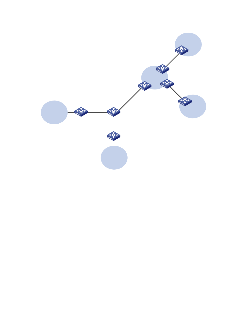
Figure 6 Network diagram
Configuration procedure
Assume that the system name of the MCE device is MCE, the system names of the edge devices of VPN
1 and VPN 2 are VR1 and VR2, and the system name of PE 1 is PE1.
1.
Configure the VPN instances on the MCE and PE 1:
# On the MCE, configure VPN instances vpn1 and vpn2, and specify an RD and route targets for
each VPN instance.
[MCE] ip vpn-instance vpn1
[MCE-vpn-instance-vpn1] route-distinguisher 10:1
[MCE-vpn-instance-vpn1] vpn-target 10:1
[MCE-vpn-instance-vpn1] quit
[MCE] ip vpn-instance vpn2
[MCE-vpn-instance-vpn2] route-distinguisher 20:1
[MCE-vpn-instance-vpn2] vpn-target 20:1
[MCE-vpn-instance-vpn2] quit
# Create VLAN 10, add port FortyGigE 1/0/1 to VLAN 10, and create VLAN-interface 10.
[MCE] vlan 10
[MCE-vlan10] port fortygige 1/0/1
[MCE-vlan10] quit
CE
VPN 1
Site 2
CE
VPN 2
Site 1
PE 1
PE 3
PE 2
VPN 2
2012::/64
VR 2
VPN 1
2012:1::/64
VR 1
MCE
FGE1/0/1
Vlan-int10
2001:1::1/64
FGE1/0/1
Vlan-int30: 30::2/64
Vlan-int40: 40::2/64
FGE1/0/3
Vlan-int30: 30::1/64
Vlan-int40: 40::1/64
FGE1/0/2
Vlan-int20
2002:1::1/64
Vlan-int10
2001:1::2/64
Vlan-int20
2002:1::2/64
Vlan-int11
2012:1::2/64
Vlan-int21
2012::2/64