Irf topology, Topology collection, Figure 6 – H3C Technologies H3C S10500 Series Switches User Manual
Page 12
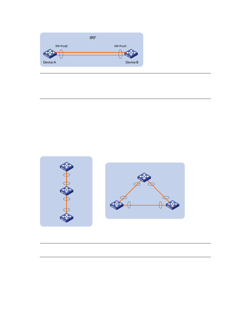
Figure 6 IRF fabric physical connection
NOTE:
•
An IRF port can be bound to a maximum of eight physical ports to increase the bandwidth and reliability
of the IRF port.
•
The links between two IRF members must be fibers, and no intermediate devices are allowed.
IRF topology
An IRF fabric typically adopts daisy chain connection or ring connection, as shown in
.
•
A daisy chain connection is mainly used in a network where member switches are distributedly
located.
•
A ring connection is more reliable than the daisy chain connection. In a daisy chained IRF fabric,
the failure of one link can cause the IRF fabric to partition into two independent IRF fabrics; where
the failure of a link in a ring connection result in a daisy chain connection, not affecting IRF services.
Figure 7 IRF connections
IRF
Ring connection
Slave Slave
Master
IRF-Port1
IRF-Port2
IRF-Port1
IRF-Port2
IRF-Port1
IRF-Port2
Daisy chain
connection
IRF
Master
Slave
Slave
IRF-Port2
IRF-Port2
IRF-Port1
IRF-Port1
NOTE:
The ring connection is supported only when the IRF fabric has three or four member switches.
Topology collection
Each member exchanges IRF hello packets with neighbors to collect the topology data, including IRF port
connection states, member IDs, priorities, and bridge MAC addresses.
6