Interface modules – ATL Telecom AM64/512 User Manual
Page 28
a
telecom
User Guide
High Speed Modems
Interface Modules :
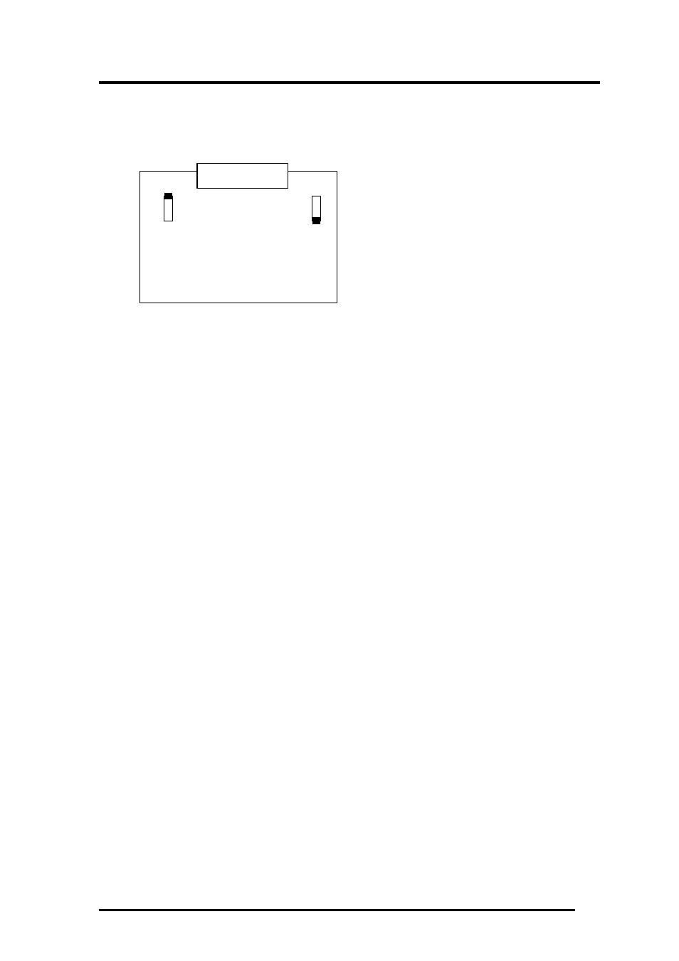
RS530 Interface Module :
J1 - T Circuit.
J2 - Circuit S ExT Termination.
J1 – V36 and RS530 Circuit 103 (Transmit data) Circuit Termination – This link connects a 120
ohm load resistor across the 103 circuit in position 1-3. This helps maintain signal rise times and
minimises reflections at greater than 9.6 kbps over long lines. At lower rates and over short lines
the termination resistor may be omitted, (link set position 1-2).
J2 – V36 and RS530 Circuit 113 (External Signal Element Timing) Circuit Termination – This link
connects a 120 ohm resistor across the 113 circuit in position 1-3. This helps maintain signal rise
times and minimises reflections at rates greater than 9.6 kbps over long lines. At lower rates and
over short lines the termination resistor may be omitted, (link set position 1-2).
X.21bis Interface Module ;
There are no links on the X.21BIS Interface module
G.703 Interface Module ;
There are no links on the G.703 interface module.
WARNING
Only authorised personnel can be allowed to open the Line Terminating Unit case to
change the link settings. Misuse or any modifications carried out to this unit other than
in accordance with the instructions supplied, will invalidate both the guarantee CE and
BABT approval.
A-7
J1 J2
SK1