1 i/o mapping, 2 update transmission times – Westermo RM-505U-2-E User Manual
Page 32
505U Radio Telemetry Module
Page 32
© September 2002
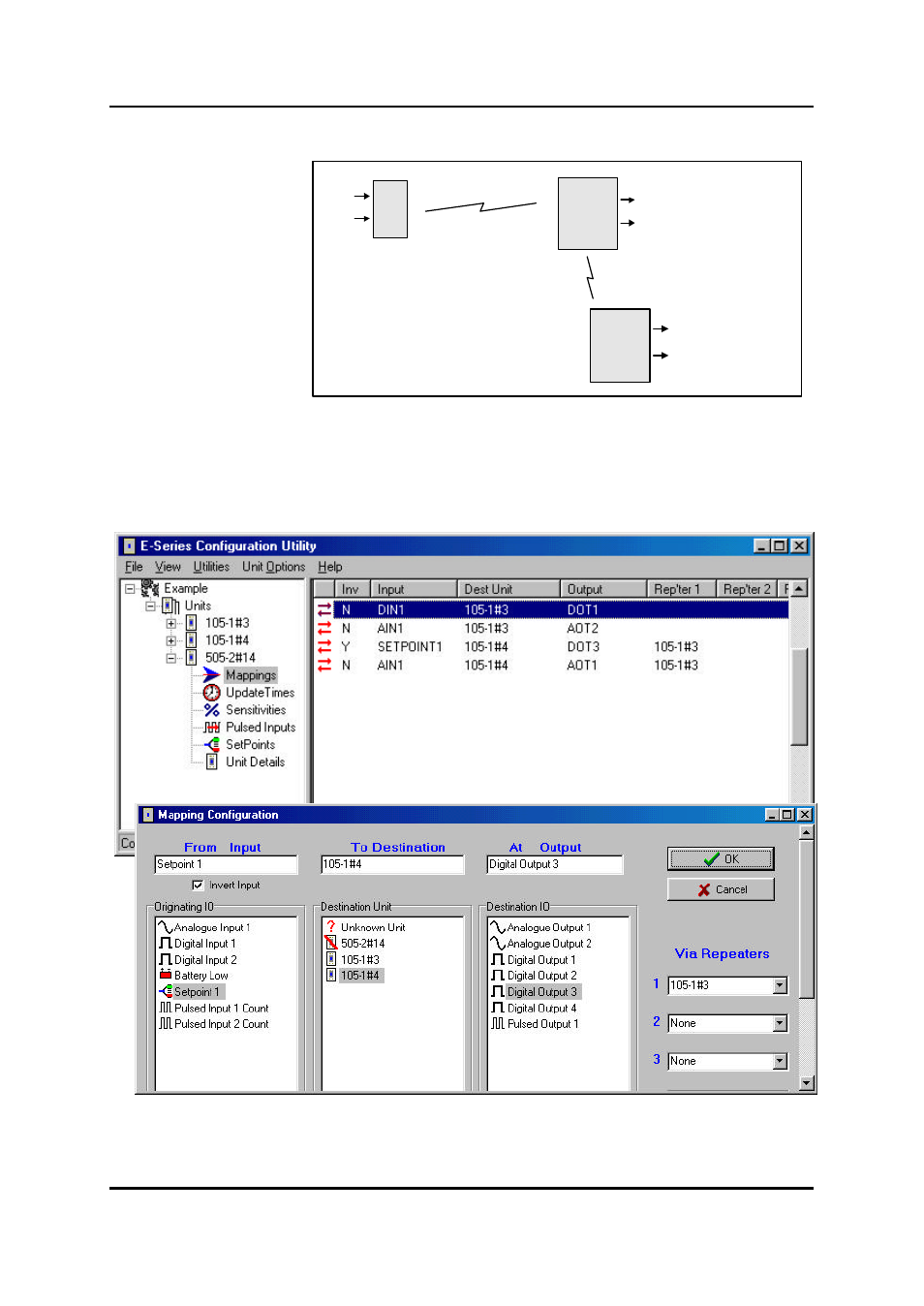
4.1 I/O Mapping
Enter I/O mappings as per
the 105U manual.
In the following example, a
digital input at a 505U is
mapped to DO1 of
105U#13. The analogue
inout of the 505U is
mapped to AO2 of the same module.
The setpoint status of the 505U is mapped (inverted) to DO3 of 105U#14, using 105U#13 as a
repeater. The 505U AI is also mapped to AO1 of this module. That is, the AI is mapped twice.
The mapping configuration for the 505U would be :
4.2 Update Transmission Times
505U
105U
105U
#14
#3
#4
DIN1
AIN
DO1 (DIN1 from #14)
AO2 (AIN from #14)
AO1 (AIN from #14)
DO3 (SP inv from #14)
See also other documents in the category Westermo Equipment:
- TR-36B (88 pages)
- TD-36 (44 pages)
- TR-36 (36 pages)
- TR-36B (20 pages)
- IDW-90 AT (97 pages)
- GD-01 (206 pages)
- GD-01 (20 pages)
- MRI-128-F4G (175 pages)
- MRI-128-F4G (169 pages)
- GDW-11 485 (380 pages)
- GDW-11 (40 pages)
- Lynx Series (28 pages)
- ODW-720-F1 (24 pages)
- ODW-720-F2 (36 pages)
- ODW-720-F1 (20 pages)
- ODW-730-F2 (36 pages)
- ODW-730-F1 (24 pages)
- DDW-120 (24 pages)
- DDW-226-EX (24 pages)
- DDW-226-EX (24 pages)
- DR-270 (28 pages)
- DR Series (460 pages)
- ED-2x0 (20 pages)
- MRD-3x0 (199 pages)
- FD-80 (24 pages)
- FDV-206-1D-1S (24 pages)
- GD-01 US (24 pages)
- LD-01 (8 pages)
- IDW-90 (44 pages)
- Lynx-x10-F2G (16 pages)
- Lynx-x08-F2G-S2 (20 pages)
- MDI-110-F3x (16 pages)
- MR-2x0 (28 pages)
- ODW-642 (28 pages)
- PII PoE Injector (12 pages)
- Viper Series (977 pages)
- SDI-5xx (12 pages)
- RFI-xx (32 pages)
- SDI-8xx (16 pages)
- RFIR-xxx (24 pages)
- TD-29 (16 pages)
- SDW-5xx (24 pages)
- TD-23 (24 pages)
- TD-29P (16 pages)
- Viper 408 (20 pages)