Westermo RM-505U-2-E User Manual
Page 30
505U Radio Telemetry Module
Page 30
© September 2002
to a PC for configuration, field testing and for factory testing. Communication is via standard RS-
232 signals. The 505U is configured as DCE equipment with the pinout detailed below.
Pin
Name
Dirn
Function
1
-
-
Not Used.
2
RD
Out
Receive Data - Serial Data Output (High = 0, Low = 1)
3
TD
In
Transmit Data - Serial Data Input (High = 0, Low = 1)
4
DTR
In
Data Terminal Ready - used by 505U as a "wake-up" signal
5
SG
-
Signal Ground
6
-
-
Not Used.
7
-
-
Not Used.
8
-
-
Not Used.
9
-
-
Not Used.
The DTR signal must be connected to the 505U to enable communications and “wake up” the
microprocessor. This means that the DTR wire must be connected - the PC does not need to
control DTR. When communications is established, the green LED will light continuously.
The serial port communicates at a baud rate of 4800 baud, 8 bits, no parity, one stop bit.
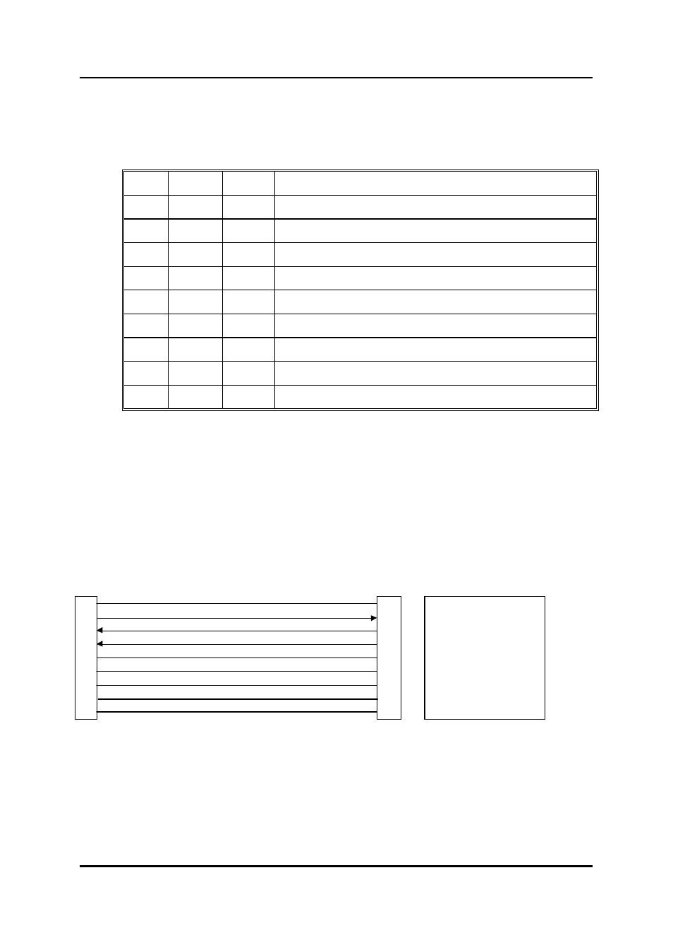
An example cable drawing for connection to a personal computer is detailed below:
E505 DB9 (M) Connector
Computer DB9 (F) Connector
1
1
Not Used - optional
2
2
Receive Data
3
3
Transmit Data
4
4
DTR
5
5
Signal Ground
6
6
Not Used - optional
7
7
Not Used - optional
8
8
Not Used - optional
9
9
Not Used - optional