Shaft encoder connections – Westermo RM-505U-2-E User Manual
Page 29
User Manual
MAN_505_1.7.DOC
Page 29
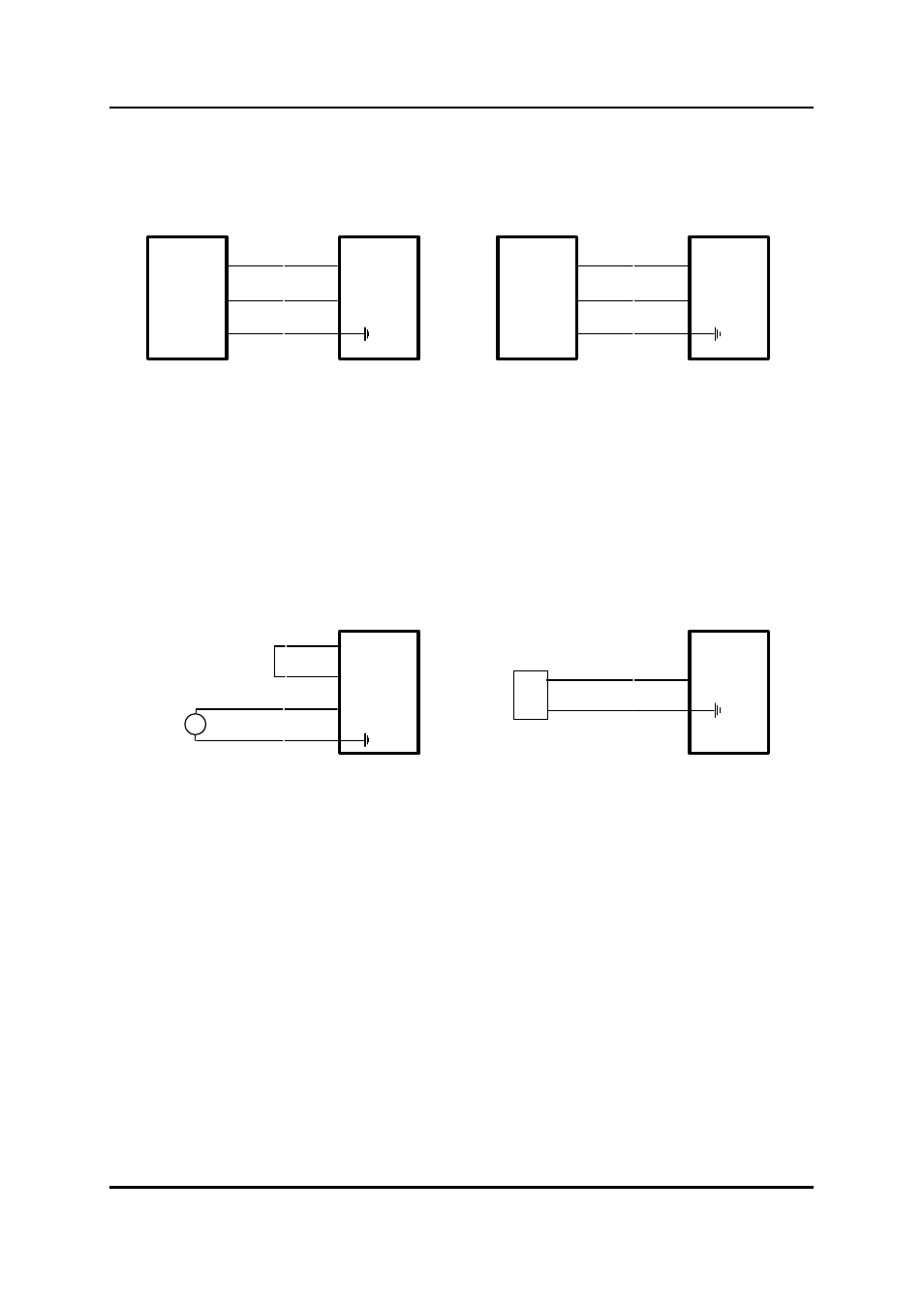
Shaft Encoder Connections
⊂
⊂
⊂
COUNT
DIRECTION
GND
DIN2
DIN1
505U-2
⊂
⊂
⊂
PHASE 1
PHASE 2
GND
DIN2
DIN1
505U-2
INCREMENTAL SHAFT ENCODER
QUADRATURE SHAFT ENCODER
3.5.2 Analogue input
The analogue input has a positive and a negative terminal, and may be placed at any point in the
current loop, as long as neither input rises more than 15V above COMMON or ground. A 12
VDC 20mA supply is provided for powering analogue loops (both 505U-E and 505U-B modules).
The analogue loop may be powered from the internal supply or may be externally powered.
⊂
⊂
GND
AI-
505U-2
⊂
⊂
+
-
AI+
505U-2
⊂
LOOP POWERED TRANSDUCER
EXT POWERED TRANSDUCER
⊂
⊂
⊂
+
-
AI+
AI-
ANALOG
SUPPLY
Loop powered transducers must be suitable for low voltage operation. Loop voltage available for
the transducer is 8.5V for 505U-B modules and 1.5V less than the power supply voltage for 505U-
E modules.
Shielded cable is recommended for analogue input loops to minimise induced noise and radio
frequency interference (RFI). The shield of the cable must be connected to earth at one end of the
cable only. Each input has a loop resistance of 150
Ω
and zener diode protection against
overvoltage and reverse voltage. Additional surge protection is recommended in high electrical
noise environments, or if the analogue signal cable runs for a long distance underground before
connecting to the 505U module.
3.5.3 RS232 serial port
An RS232 port is provided for connection of a PC for configuration and diagnostics. To access the
serial port DB9 connector, remove the front cover from the module by unscrewing the four screws
in the front panel. The serial port is a 9 pin DB9 male and provides for connection to a terminal or