Power supply installation – Westermo RM-505U-2-E User Manual
Page 26
505U Radio Telemetry Module
Page 26
© September 2002
Power Supply Installation
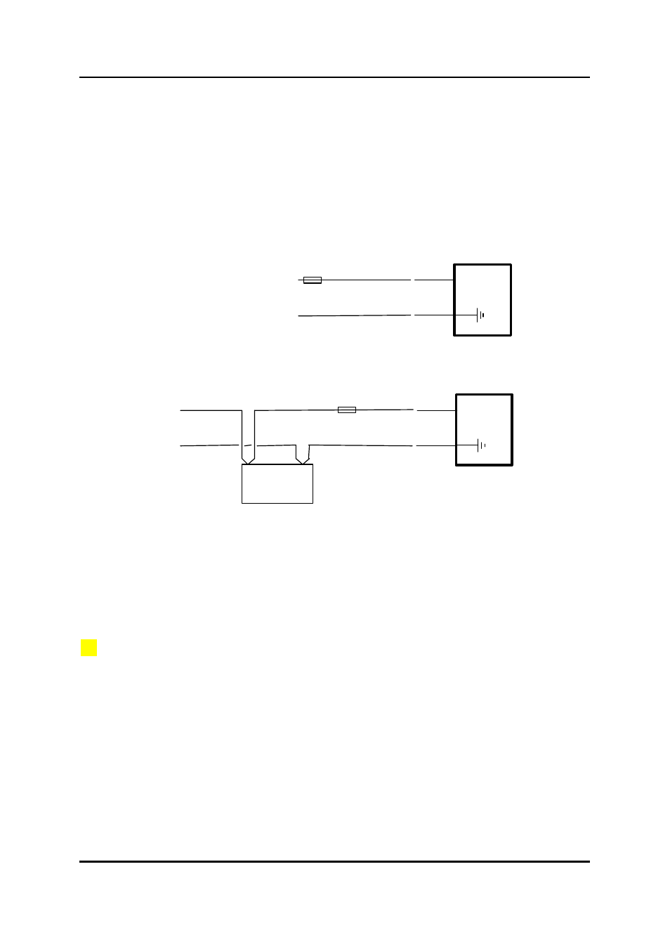
3.4.1 External Power
The 505U module will accept an external supply of 11.5 - 15.0 volts DC. An external supply with a
battery and battery charger is suitable. Negatively grounded or floating supplies are acceptable,
however positively grounded supplies must not be connected. The 505U connects the negative
supply (COMMON) to “ground”. Connect the external supply as per the following diagram.
⊂
⊂
+
-
11 - 15 VDC
505U
EXT
SUPPLY
GND
500mA
⊂
⊂
+
-
BATTERY
CHARGER
505U
EXT
SUPPLY
GND
500mA
12V
BATTERY
3.4.2 Internal Battery Power
To install internal batteries, remove the module cover by unscrewing the four screws on the front
panel.
Two battery options may be installed:
•
3 x lithium AA, 1.5V batteries, e.g. Energiser L91
•
3 x alkaline AA, 1.5V batteries, type Duracell MN1500B4, Eveready E91, or equivalent
Lithium batteries would normally be used where the module is likely to experience temperature
extremes, Lithium batteries can operate down to –40
0
C
An optional external battery pack Model BU-5-1, using 6 x AA Batteries of either the above types
(can be used with internal batteries installed or not)
Caution: Never mix two types of battery (Lithium & Alkaline), always replace a full set of batteries.
Configuration of the module will not be lost when batteries are removed, so no special procedure is
required when replacing batteries.