Watson-Marlow 505Di User Manual
Page 3
3
DO run at a slow speed when pumping viscous fluids. When using the 501RL pumphead, a 4.8 or 6.4mm bore tube with
a 1.6mm wall will give best results. Tube diameter smaller than this will generate a high -friction pressure loss, so
reducing the flow. Tube with a larger bore will not have sufficient strength to restitute. Flooded suction will enhance
pumping performance in all cases, particularly for materials of a viscous nature. Silicone, Marprene and Neoprene tubing
is available with a 2.4mm wall thickness for speeds up to 200rpm. (The rotor will require re-setting to a roller/track gap of
3.8mm.)
DO fit an extra length of pump tube in the system to enable tube transfer. This will extend tube life and minimise the
downtime of the pumping circuit.
DO keep the track and rollers clean.
The self-priming nature of peristaltic pumps means valves are not required. Any valves fitted must cause no restriction to
flow in the pumping circuit.
When using Marprene tubing, after the first 30 minutes of running, re-tension the tube in the pumphead by releasing
the tube clamp on the delivery side a little and pulling the tube tight. This is to counteract the normal stretching that
occurs with Marprene which can go unnoticed and result in poor tube life.
Tube selection The chemical compatibility list published in the Watson- Marlow catalogue is only a guide. If in doubt
about the compatibility of a tube material and the duty fluid, request a tube sample card for immersion trials.
Installation
The 505Di is suitable for single phase mains electricity supplies only.
To ensure correct lubrication of the gearbox the pump should be run only while its feet are standing on a horizontal
surface. The pump should be positioned to allow a free flow of air around it.
•
Set the voltage selector to either 120V for 100-120V 50/60Hz supplies or 240V for 220-240V 50/60Hz supplies.
A mains cable fitted with a moulded plug is supplied with the pump. The wires are colour coded in accordance with the
following code:
•
220-240V: Live- Brown; Neutral - Blue; Earth - Green/Yellow.
•
100-120V: Live - Black; Neutral - White; Earth - Green.
Reduced voltage operation
In areas where voltage is below that specified above, modifications can be made to the pump unit to allow operation
under the following minimum voltage levels:
•
180V when using the 220-240V setting.
•
90V when using the 100-120V setting.
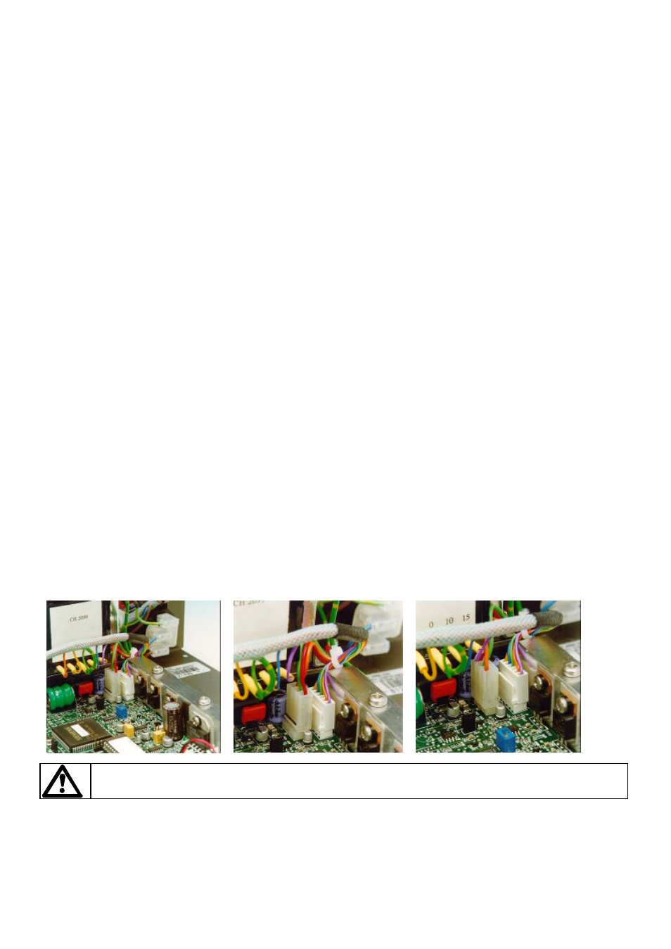
The modification requires the connector J8 on the Control PCB to be reversed. To locate the terminal, isolate the mains
supply then remove the pump cover. State A shows the standard voltage setting, whilst State B shows the reduced
voltage setting. Any damage caused to the pump in the process of carrying out this modification will not be covered by
warranty.
Control PCB
State A
State B
Refer servicing to qualified personnel only.
Troubleshooting
Should the pump fail to operate, make the following checks to determine whether or not servicing is required.
•
Check that the power switch is on.
•
Check the mains supply is available at the pump.