Watson-Marlow 505Di User Manual
Page 10
10
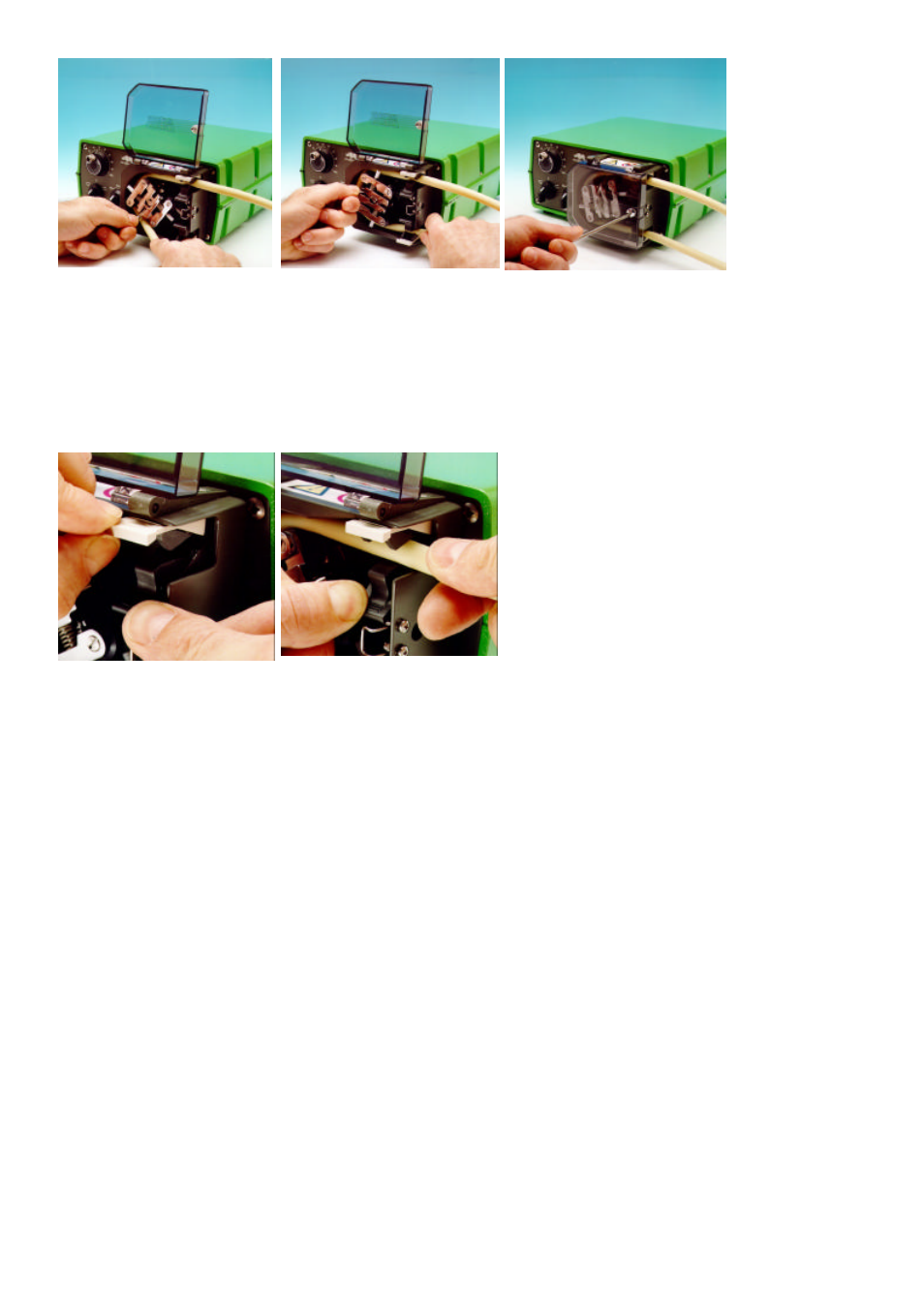
Fit the other end of the tubing into the second spring loaded clamp, ensuring that the tubing is not slack in the
pumphead, since this can reduce tube life.
Close the crank handle and shut and lock the guard.
After the pump has been started, open the downstream clamp for a short time, so that the tube can find its natural
length.
The 501RL pumphead is fitted with four-position tube clamps, to accommodate various tube diameters, which can be
adjusted by pushing in or pulling out the bars at the top of the upper clamp and the bottom of the lower clamp. Set the
clamps so that the minimum necessary pressure is applied to the tubing.
Roller adjustment
The 501RL has a factory set gap of 2.6mm between the rollers and the track and is suitable for tubing having wall
thicknesses of between 1.6 and 2.0mm. Adjustment of the gap will be required if tubing having a wall thickness of less
than 1.6mm is required. There is an adjusting screw on each of the two roller arms, and each of these screws will require
adjustment. The correct gap is twice the wall thickness less twenty percent. Correct adjustment is important: over
occlusion will reduce tube life; under occlusion will reduce pumping efficiency.
To change the gap setting, turn each adjusting screw clockwise to increase the gap, or anticlockwise to decrease the
gap. A full turn changes the gap by 0.8mm.
To restore the original settings of 2.6mm, turn the adjusting screws until both rollers are just touching the track, then
tighten each screw by three and a quarter turns. The 501RL2 has a factory set gap of 3.8mm between the wall and the
track and is suitable for tubing having wall thickness of between 2.1 and 2.5mm.
Check moving parts of the rotor from time to time for freedom of movement. Lubricate pivot points and rollers occasionally
with Teflon lubricating oil.