Varmeca - 20, Variable speed motor or geared motor, 4 - commissioning – Watson-Marlow Varmeca User Manual
Page 30: 5 - faults - diagnostics, 1 - varmeca - 20, 2 - varmeca - 20 with remote potentiometer option
28
INSTALLATION AND MAINTENANCE
VARMECA - 20
Variable speed motor or geared motor
COMMISSIONING
LEROY-SOMER
Réf. 3481 - 4.33/c - 09.01
4 - COMMISSIONING
• Before switching on the VARMECA - 20 motor,
check that the electrical connections are
correct, and that any moving parts are mechanically
protected.
• For the safety of personnel, the VARMECA - 20
must not be switched on with the protective cover
removed.
• The run command has been enabled, thus the
motor starts as soon as it is switched on.
4.1 - VARMECA - 20
4.1.1 - Starting with remote control
- Power-up: Terminals 1 and 3 are connected.
- Activate the run command corresponding to the required
direction. The motor starts.
- Adjust the speed reference using the chosen reference
(0/10V or 4/20mA).
4.1.2 - Starting on power-up with the speed
control knob option
- Power-up: The green indicator lamp is on continuously. As
control terminals 1 and 3 (enable) and 8 and 10 are
connected together, the motor starts running forward.
- Set the speed reference using the side control knob.
4.2 - VARMECA - 20 with remote
potentiometer option
- Power-up: Terminals 1 and 3 are connected.
- Select the required ramp.
- Set the reference using the 10 k
Ω
remote potentiometer.
- Select the required direction of rotation. The motor starts.
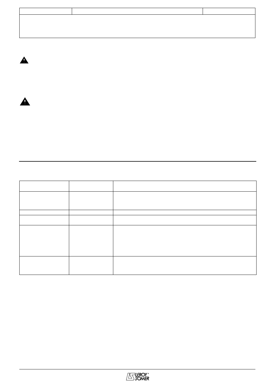
5 - FAULTS - DIAGNOSTICS
Information relating to the status of the VARMECA - 20 is provided by 2 indicator lamps located on the control options.
Trips can be cleared by switching off the VARMECA - 20
.
Colour and state of
indicator lamps
Reason for fault
Checks to be performed
Steady green
No fault
Mains present
If the motor does not rotate, check that:
- terminals 1 and 3 are connected
- a run command has actually been enabled: terminals 7 and 10 or 8 and 10
are connected
Flashing green and red
Current limiting
• Check that the motor is not overloaded or stalled
Flashing green
Overload
• The motor is overloaded: check the motor current using a clamp ammeter
(section 6.2.2)
Steady red
• Short-circuit of a
motor winding
• Locked motor rotor
• Faulty insulation
of a winding
• I
2
t overheating
• Internal fault
• Check that no incident has occurred
• Switch off and then on again to clear the fault
• Check that the deceleration ramp is long enough (5s) for applications with
high inertia
• If the fault remains, consult LEROY-SOMER
Flashing red
• Undervoltage
• Overvoltage
• Check the mains voltage
• Check that the deceleration ramp is long enough (5s) for applications with
high inertia
• Switch off and then on again
COMMISSIONING & FAULTS - DIAGNOSTICS