Varmeca - 20, Variable speed motor or geared motor, 2 - installation – Watson-Marlow Varmeca User Manual
Page 26: 1 - general, 2 - reversing the supports, Leroy-somer
24
INSTALLATION AND MAINTENANCE
VARMECA - 20
Variable speed motor or geared motor
INSTALLATION
LEROY-SOMER
Réf. 3481 - 4.33/c - 09.01
1.4 - Environmental characteristics
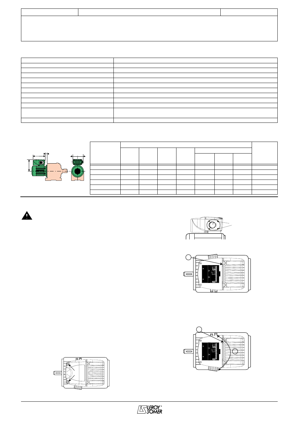
1.5 - Weights and dimensions
Characteristics
Level
Protection index
IP 65
Storage temperature
-40°C to +70°C (IEC 68.2.3)
Transport temperature
-40°C to +70°C
Operating temperature
-20°C to +40°C (+50°C with derating)
Altitude
≤
1000 m without derating
Ambient humidity
Without condensation
Vibration
IEC 68-2-34 (acceleration 0.01 g
2
/Hz)
Shocks
IEC 68-2-27 (peak acceleration 20g)
Immunity
Conforming to EN 50082-2
Radiated conducted emissions
• Conforming to EN 50081-2 as standard
• Conforming to EN 50081-1 with EMC filter option for the VMA 21 M range
UL standard
Conforming to FILE E211799
Type
Dimensions in mm
Weight of
VARMECA
(kg)
HJ
J
I
II
LJ
B3/B14
B5
B5 with
gearbox
LS 71 L
181
216
75
94
8
8
34
4.2
LS 80 L
191
216
75
94
12
12
39
4.2
LS 90 S and L
201
216/230
75
94
12
32
32
4.2
LS 100 L
206
230
75
94
12
12
33
4.2
LS 112 M
206
230
75
94
12
12
33
4.2
LS 112 MG
215
230
75
94
20
20
16.5
4.2
J
LJ
HJ
I
II
2 - INSTALLATION
• It is the responsibility of the owner or user to
ensure that the installation, operation and
maintenance of the inverter and its options comply with
legislation relating to the safety of personnel, animals
and equipment, and with the current regulations of the
country of use.
• Before carrying out any work, disconnect and lock
the drive power supply. For the single-phase range, wait
2 minutes to make sure that the capacitors have
discharged.
• After connection, ensure that the seals are firmly
in place, and that the screws and cable glands are
watertight to ensure IP 65 protection. Clear any
condensation from the drain holes at the bottom of the
motor.
2.1 - General
The VARMECA - 20 is fitted to the machine like a standard
motor, with flange or foot mounting.
The motor fan cools the whole assembly. Make sure that the
ventilation air inlet is free of obstruction.
The positions of the potentiometer/cable gland supports are
specified at the time of ordering. However they may be
reversed if necessary.
2.2 - Reversing the supports
1) Undo the 2 TORX 20 + slot type screws and remove the
cover.
2) Remove the control knob and cable gland support
fastening screws (TORX 10 + slot type screws).
3) Disconnect the layer from the P2 connector if an option is
connected.
4) Reverse the option and cable gland supports.
5) Reconnect the printed circuit layer on P2 and replace the
fastening screws.
6) Replace the cover.
TORX 10
+ slot screw
3
ST
AND
ARD CONFIGURA
TION
1
2
3
4
5
6
7
8
9
10
24V
5s
2s
24V
10V
0V
11
12
L1
L2
L3
PE
R1
R2
≥
50
Ω
10k
Ω
V
A
LID
A
TION
ENABLE
FREIGA
GE
0 - 10V
4 - 20mA
200V -10%
480V +10%
CA
UTION
A
TTENTION
A
CHTUNG
Bef
o
re maintenance
A
v
a
nt inter
vention
V
or jeglic
hem eingriff
wait 2 min
u
tes
a
ttendre 2 min
u
tes
2
min
u
ten war
ten
DEF
A
UT
FA
U
LT
STÖR
UNG
RESEA
U
SUPPL
Y
NETZ
A
CCEL
DECEL
CONFIGURA
TION OPTION
CONSUL
TER LA NO
TICE D'INST
ALLA
TION
SEE INST
ALLA
TION MANU
AL
BITTE INBETRIEBNAHME
SEHEN
P2
4
5
ST
AND
ARD CONFIGURA
TION
1
2
3
4
5
6
7
8
9
10
24V
5s
2s
24V
10V
0V
11
12
L1
L2
L3
PE
R1
R2
≥
50
Ω
10k
Ω
V
A
LID
A
TION
ENABLE
FREIGA
GE
0 - 10V
4 - 20mA
200V -10%
480V +10%
CA
UTION
A
TTENTION
A
CHTUNG
Bef
o
re maintenance
A
v
a
nt inter
v
ention
V
o
r jeglic
hem eingriff
wait 2 min
u
tes
a
ttendre 2 min
u
tes
2
min
u
ten war
ten
DEF
A
U
T
FA
U
LT
ST
Ö
R
UNG
RESEA
U
SUPPL
Y
NETZ
A
CCEL
DECEL
CONFIGURA
TION OPTION
CONSUL
TER LA NO
TICE D'INST
ALLA
TION
SEE INST
ALLA
TION MANU
AL
BITTE INBETRIEBNAHME
SEHEN
P2
GENERAL INFORMATION & INSTALLATION