Software configuration – Verilink PRISM 4151 (34-00258) Product Manual User Manual
Page 14
3-2 Configuration
PRISM 4151
CTS Delay: Switch S2-5 allows you to determine the CTS
delay as being either Short (Dn) or Long (Up).
RTS, CTS, DCD Handshake: Switch S2-6 determines the
handshake process as either Force True (Dn) or Normal
(Up).
Remote/Local Loop: Switch S2-7 disables (Dn) or enables
(Up) remote and local loop activation by the RL and LL pins
on the DTE interface.
DTE Alarm: Switch S2-8 disables (Dn) or enables (Up) the
DTE alarm. The DTE alarm is generated when DTR from
the DTE device is false.
Software Configuration
The terminal interface is a firmware application program
embedded inside the PRISM 4151. You can access this
information through the LAN port (page 2-2), SUPV port
(page 2-3), or SLIP port (page 2-3) using a TELNET ses-
sion.
Interface Start-up
Once a compatible terminal is properly connected to the
unit, you can start a terminal interface session by sending a
BREAK command to the unit (or by pressing
times). If a password has been previously establish, you
must enter the correct password to continue the session. The
password is case-sensitive. If you have forgotten your pass-
word, note the date and time shown on your screen and con-
tact TxPORT Technical Support. You can establish a
password through the Utilities screen on page 3-10.
Once a valid password has been entered, the Main Menu
screen is displayed. If you are unfamiliar with the PRISM
4151 interface, commands, and menu structure, refer to
Appendix A, Terminal Interface, for specific information
concerning the menu structure and operator commands.
If you do not enter a keystroke for
10 minutes, the terminal interface
automatically logs off.
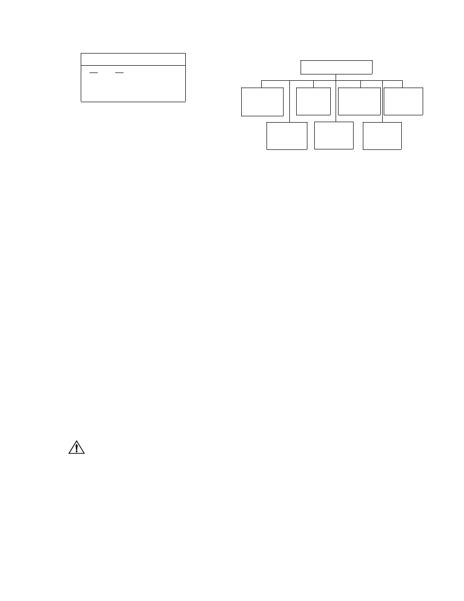
Configuration Screen
The Configuration screens allow you to view and set config-
uration parameters for the network elements.
To send a new configuration to the unit, you must
press
screen. The underlined values are the factory
default parameters.
Table 3-H Timing Source
S2-3 S2-4 Timing
Source
Dn
Dn
Network
Dn
Up
Internal
Up
Dn
DTE
Up
Up
Not Used
Alarm
Configuration
page 3- 5
DTE Port
Parameters
page 3-4
SNMP
Configuration
page 3-7
Configuration Menu
Summary
page 3-9
TCP/IP
Configuration
page 3- 6
Management
Ports
page 3-8
Figure 3-9 Configuration Menu
DDS Network
Parameters
page 3-3