Net led, Test procedures, Verifying a t1 – Verilink NCC 2130 (880-503285-001) Product Manual User Manual
Page 50: Net led -8, Test procedures -8, Verifying a t1 -8
Diagnostics
5-8
Verilink NCC 2130 User Manual
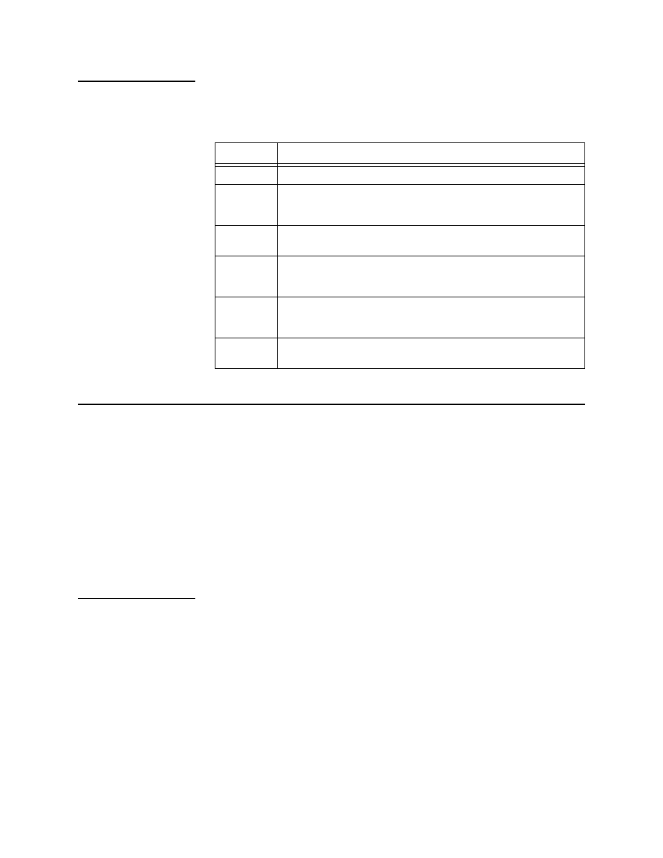
NET LED
The NET (network) LED is a tri-color indicator with six states, as
follows:
Table 5-5 Net LED States
Test Procedures
Testing can be divided into two categories, tests which are
conducted to verify an installation where no known problems exist;
and tests which result from an effort to troubleshoot a problem
known to exist. Two procedures are described below.
•
First, in the section “
”, a method is described to
test a T1 circuit when it is expected that no trouble will be
found.
•
Then, in the section “
”, a suggested method
for finding T1 problems is detailed.
Verifying a T1
For this procedure, a pattern is sent from a local CSU, through the
entire transmit path of the T1 circuit, to a loopback in a far end
CSU, then back through the other direction of the T1 circuit.
A loop-up code is sent, then a test pattern is transmitted.
The data received from the T1 circuit is compared to the data
transmitted. If the data received is identical to the data
transmitted, the T1 is good and can be placed into service.
Far End Loop
To begin the verification, use the Inband Up command on the
Diagnostics Menu. This causes the local CSU to transmit a loop-up
code in the direction of the far end CSU
State
Meaning
Solid Green A normal signal is being received from the network (all OK).
Solid
Yellow
The NCC is looped toward the network via a line loopback (LLB)
or payload loopback (PLB) and no errors are being received from
the network.
Solid Red
Continuous errors are being received on the network interface
(e.g., LOS, LOF, RAI, AIS).
Flashing
Red to
Green
Bipolar violations or CRC-6 errors are being received on the
network interface.
Flashing
Red to
Yellow
The CSU is looped toward the network and errors are being
received (BPV or CRC-6).
Not Lit
The NCC has no power or, if other LEDS are lit, the NCC is
defective.