Test procedures, Verifying a t1, Test procedures -8 – Verilink NCC 2020 (880-503284-001) Product Manual User Manual
Page 56: Verifying a t1 -8
Diagnostics
5-8
Verilink NCC 2020 User Manual
Test Procedures
Testing may generally be divided into two categories, tests which
are conducted to verify an installation where no known problems
exist; and tests which result from an effort to troubleshoot a
problem known to exist.
Two procedures are described below. First, in the section
“
, a method is described to test a T1 circuit when it
is expected that no trouble will be found. Then, in the section
“
”, a suggested method for finding T1 problems is
detailed.
Verifying a T1
For this procedure a pattern will be sent from a local CSU, through
the entire transmit path of the T1 circuit, to a loopback in a far end
CSU, then back through the other direction of the T1 circuit.
First a loop-up code is sent, then a test pattern is transmitted.
The data received from the T1 circuit will be compared to the data
which was transmitted. If the data received is identical to the data
which was transmitted, the T1 is good and may be placed into
service.
Far End Loop
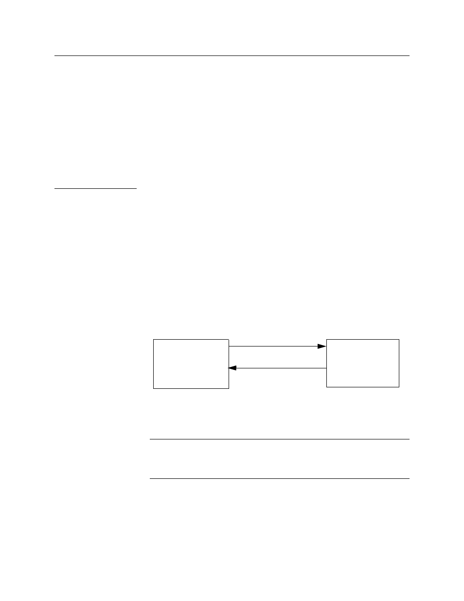
To begin the verification, use the Inband Up command on the
Diagnostics Menu. This causes the local CSU to transmit a loop-up
code in the direction of the far end CSU
Figure 5-3
Sending Loop-up Code.
If the loop-up code reaches the far CSU and it is optioned to
respond to loop-up codes, then the far CSU enters a line loop
condition. Now the local CSU receives whatever it is sending.
NOTE: Whenever the Inband Up command is used to send a loop-up
code to a far end CSU, the Inband Down command must be
used later to send the loop-down code. Otherwise the far end
CSU will be left in a looped condition.
Sending a Pattern
Begin transmitting a test pattern by using the qrss command.
Verify that the pattern received matches the pattern being
transmitted by using the show cntr command.
Loop-up code
Far CSU
Local NCC 2020