Nearpayloadloop, Near payload loop -10, Near payload loop – Verilink 1558D (34-00255) Product Manual User Manual
Page 36
LAPS Operation 4-10
1558D APS CSU/DSU
2. From the Maintenance screen, decide which Path is to be
looped (A or B path).
3. If necessary, force the 1558D to use the Path (A or B)
that is not to be looped.
4. Lock this Path (A or B). This prevents the 1558D from
switching the active path to the test path during testing.
The LAPS software and 1558D
hardware will not allow a user to
loop an active line or apply a BERT pat-
tern to an active line. Only a line shown
in the StandBy mode or Inhibited mode
can be looped or BERT tested.
5. Initiate the desired local/remote loop.
The following sections describe in detail how to perform
loops and unloops of the 1558D equipment. Note that all
loops and unloops are performed at the Maintenance screen.
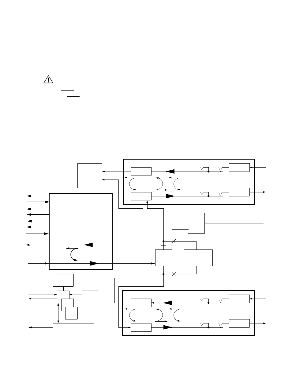
The location of the various loops is depicted in the 1558D
Block Diagram shown in Figure 4-10. The remainder of this
chapter discusses these loops. The user should refer to the
block diagram mentioned earlier for a clearer understanding
of the loop that is being described by this material discussed
in the following paragraphs.
Near Payload Loop
Target the path (A or B) that you want to test by moving the
cursor highlight to the Target field and then, using the space
bar, toggle the field until it displays the SIDE that you want
to loop (Side A or Side B). After you have selected either
the A or B side as the target for testing, move the cursor
highlight to the Loop field and toggle the field, using the
space bar, until the field displays Near Payload. Then,
momentarily depress the
tiate a payload loop of the selected target. After a few
moments, notice that the NEAR status field has changed
from Soft Inhibit or StandBy to PL LP. Also note that the
near 1558D front panel Loop LED indicator is on.
A payload loopback loops the incoming T1 signal back to
the network. The T1 signal is regenerated (both CRC and
signal level). In addition to looping the signal back to the
network, the signal is also passed to the 1558D DTE port.
Figure 4 -10
1558D Block Diagram
B
NET
Power
COM Bus
Rx
Supply
±12 VDC
+5 VDC
Tx
Line
Deframer
NET A
Framer
Loop
Line
Protection
Fac/Local
Loop
PLB
APS
Select
Path A/B
Bridge
Jack
Receive
Jack
NET A
Bridge
Jack
Transmit
Jack
A
RJ48
Line
Protection
NET
Rx
Tx
Line
Deframer
NET B
Framer
Loop
Line
Protection
Fac/Local
Loop
PLB
Bridge
Jack
Receive
Jack
NET B
Bridge
Jack
Transmit
Jack
B
RJ48
Line
Protection
Eq/V.54
Loop
Signal
Split
A
ROM
RAM
CPU
Loop
Set/Reset
SUPV
Port
Performance History,
Alarms, Unit Address
OUT
COM Bus
IN
Alarm
Contacts
(COM,
NO, NC)
BERT: QRSS,
1:8, 3:24, etc.
NET B
NET A
V.35 Interface
SD
RD
Tx Clk
Ext Clk
RTS
CD
DSR
TM
Rx Clk
AC Input, 110 VAC