Alarmconnections, T1connections, Combusconnections – Verilink 1558D (34-00255) Product Manual User Manual
Page 10: V.35 interface, Alarm connections, T1 connections, Com bus connections
Installation 2-2
1558D APS CSU/DSU
wire from the rear panel screw terminal labeled ‘GND’ to a
good earth ground.
Voltages in excess of 100 VDC may be
present on the T1 telecommunications
lines. Before connecting the APS unit to tele-
communication lines, ensure that the rear
panel screw terminal labeled ‘GND’ has been
connected to a good earth ground.
Alarm Connections
The 1558D has alarm contacts provided at the rear panel
screw terminals labeled ‘COMMON’, ‘NC’, and ‘NO’. The
alarm relay is operated when power is present to the 1558D.
To connect the APS alarm relay to an external customer
alarm surveillance system, perform the following:
• Connect a 26-gauge wire to the rear panel screw terminal
labeled ‘COMMON’ to the external alarm system.
• Connect a 26 -gauge wire to the rear panel screw terminal
labeled ‘ALARM NO’ (normally open) or to ‘ALARM NC
(normally closed) to the external alarm system. The alarm
relay is normally operated when power is connected to the
unit.
T1 Connections
All T1 lines are connected to the 1558D unit using modular
8-pin RJ-48 cables (two 10' RJ-48 cables come with the
unit). Insert the RJ48 connectors into the rear panel recepta-
cles labeled NET A, and NET B. Connect the other ends of
the cable to the appropriate external T1 A and B facility
equipment. The modular RJ-48 Pinouts and their functions
are shown in Table 2-C.
COM Bus Connections
The rear panel COM BUS connectors (IN/OUT) are used to
communicate to/from the optional APS 1559 site manager.
These connections are only used when a 1559 Network
manager is co-located with the 1558D(s). Bus connections
from the manager to one or more 1558D units is done in a
daisy chain fashion. That is, the COM BUS Out from the
1559 is connected to the COM BUS IN of the 1558D and
the COM BUS OUT of the 1558D is connected to the COM
BUS IN of the 1559. Physically, the connections to the
COM Bus IN/OUT are RJ-11, 6-pin miniature modular
jacks. The function of the six pins associated with the jacks
are shown below in Table 2-D.
V.35 Interface
The 1558D high speed DTE port is a 34-pin female connec-
tion. The interface is fully compatible with CCITT V.35
standards. To connect external CPE equipment to the
1558D, simply attach a male V.35 cable to the V.35 DTE
port found at the rear of the 1558D. Be sure to mechanically
secure the cable in place by tightening the provided thumb
screws. The operating speed and clocking arrangements are
described in the section entitled Configuration Modes on
page 2-3. The pinouts for the V.35 interface are shown in
Table 2-E.
Table 2-C RJ-48 Pinouts
Pin
NET A & B, RJ-48
1
Data In, Tip
2
Data In, Ring
3 Not
Used
4
Data Out, Tip
5
Data Out, Ring
6 Not
Used
7 Not
Used
8 Not
Used
Table 2-D RJ-11 Pinouts
PIN
COM BUS IN
COM BUS OUT
1
Not Used
Not Used
2
Signal Ground
Signal Ground
3
Data, output
Data, Output
4
Data, input
Not Used
5
Signal Ground
Signal Ground
6
Not Used
Not Used
Table 2-E V.35 Pinouts
Function
CCITT
Name
Direction
DTE/DCE
1558D
V.35
Frame Ground
101
FG
A
Signal Ground
102
SG
B
Send Data
103
SD
P, S
Receive Data
104
RD
R, T
Request to Send
105
RTS
C
Clear to Send
106
CTS
D
Data Set Ready
107
DSR
E
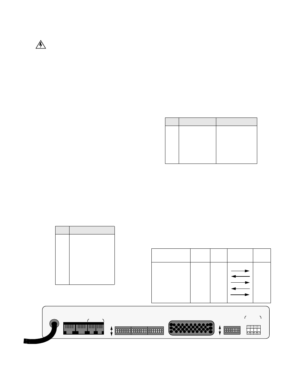
Figure 2-1 1558D Rear View
COM BUS
NET B
NET A
IN
OUT
GND
N.
O
.
COM
N.
C.
ALARM
S1
S2
S3
S4
ON
OFF
ON
OFF
V.35