Optionswitchs3, Option switch s4, Option switch s3 -4 option switch s4 -4 – Verilink 1558D (34-00255) Product Manual User Manual
Page 12
Installation 2-4
1558D APS CSU/DSU
O
PTION
S
WITCH
S3
Switch S3 is an eight position DIP switch used to configure
the 1558D unit address ID for the NET A hardware and the
NET B hardware. Unique addresses must be optioned for
each 1558D unit when multiple units are co-located and a
1559 Site Manager is being used. If no manager is being
used, the user should leave the DIP switches in the factory
default positions (all in the OFF or DOWN position). This
configures the unit for NET A address 1 and NET B address
2. Table 2-H indicates how to configure the address settings
for the first six 1558D units.
When connecting to the SUPV port using the
APS local access software, the 1558D NET A
and NET B addresses are viewed as a single unit
address and are displayed as 1.01 for addresses
1 and 2, 1.02 for addresses 3 and 4, etc.
O
PTION
S
WITCH
S4
Switch S4 is a ten position DIP switch used to configure the
following DTE interface options.
• Set DSU Operating Speed (56kb - 1.536 Mbps)
• Set Rate Multiple, 56kb or 64kb
• Set DS0 Assignment Mode, Contiguous/Alternate
• Set Flow Control, On/OFF
• Set Data Invert, Yes/No
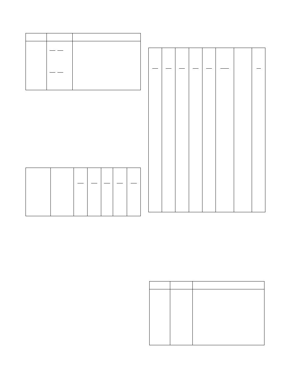
Switch 4, (Pos. 1 - 6) - These six DIP switches allow the
user to select the operating speed of the 1558D DTE port
and whether or not the DS0s are assigned sequentially,
beginning with DS0#1 or Alternately, beginning with
DS0#1, 3, 5, etc. The table below shows the option position
settings for the various combinations of speed and DS0
channel assignments. The 1558D can be configured to oper-
ate from 56 kb to 1.536 Mbps.
Switch 4 (Pos. 7 - 10) - These option switches are used to
set the following:
• Contiguous or Alternate DS0 assignment
• Set control lines to either ON or OFF
• Enable or disable data invert feature
Table 2-J displays the various options/positions controlled
by SW4, positions 7 - 10.
5,6
Off, Off
Off, On
On, Off
On, On
NET A LBO Value
0.0 dB
7.5 dB
15.0 dB
22.5 dB
7,8
Off, Off
Off, On
On, On
On, Off
Network Clocking
Network Clocking
Internal Clocking
External DTE Clocking
Table 2-H Address Settings
*APS Mgr.
Unit Pos.
NET A/B
Address
Pos
1
Pos
2
Pos
3
Pos
4
Pos
5 - 8
1.01
1/2
Off
Off
Off
Off
Off
1.02
3/4
On
On
Off
Off
Off
1.03
5/6
On
Off
On
Off
Off
1.04
7/8
On
On
On
Off
Off
1.05
9/10
On
Off
Off
On
Off
1.06
11/12
On
On
Off
On
Off
Table 2-G Switch S2
Position Selection
Switch S2 Description
Table 2-I Speed Settings
Pos
1
Pos
2
Pos
3
Pos
4
Pos
5
Pos 6
Off
(64Kb)
Pos 6
On
(56Kb)
DS0
Off
Off
Off
Off
Off
1536
1344
24
Off
Off
Off
On
Off
1472
1288
23
On
Off
Off
On
Off
1408
1232
22
Off
On
Off
On
Off
1344
1176
21
On
On
Off
On
Off
1280
1120
20
Off
Off
On
On
Off
1216
1064
19
On
Off
On
On
Off
1152
1008
18
Off
On
On
On
Off
1088
952
17
On
On
On
On
Off
1024
896
16
Off
Off
Off
Off
On
960
840
15
On
Off
Off
Off
On
896
784
14
Off
On
Off
Off
On
832
728
13
On
On
Off
Off
On
768
672
12
Off
Off
On
Off
On
704
616
11
On
Off
On
Off
On
640
560
10
Off
On
On
Off
On
576
504
9
On
On
On
Of
On
512
448
8
Off
Off
Off
On
On
448
392
7
On
Off
Off
On
On
384
336
6
Off
On
Off
On
On
320
280
5
On
On
Off
On
On
256
224
4
Off
Off
On
On
On
192
168
3
On
Off
On
On
On
128
112
2
On
On
On
On
On
64
56
1
Table 2-J Switch SW4-7 thru SW4-10
Position Selection
Switch S4 Description
7
Off
On
Contiguous DS0s
Alternate DS0s
8
Off
On
Control Lines (CTS, DSR,CD) are set
to On
Control Lines follow (DSR follows T1
sync, CTS follows RTS, and CD fol-
lows T1 density status)
9
Off
On
Data Invert Disabled
Data Invert Enabled
10
—
Not Used